
Light emitting diode lamp

a technology of light-emitting diodes and led lamps, which is applied in the direction of semiconductor devices for light sources, lighting and heating apparatus, coatings, etc., can solve the problems of reducing the lifespan of the light-emitting diode package itself, incandescent lamps, and the replacement of the electric bulb socket that has been installed, so as to increase the commercial value of the led lamp, the effect of increasing the lifespan of the light-emitting diode packag

Inactive Publication Date: 2015-05-19
G&C CO LTD +1
View PDF6 Cites 0 Cited by
  • Summary
  • Abstract
  • Description
  • Claims
  • Application Information

AI Technical Summary

Benefits of technology

This solution improves heat radiation efficiency, extends the lifespan of LED lamps, reduces manufacturing costs, and maintains light quality while being compatible with existing incandescent lamp sockets.

Problems solved by technology

However, since the LED incandescent lamp used in various fields such as home illumination, office illumination, factory illumination, a streetlamp, a fishing lamp, scene illumination, illumination for leisure facilities is driven at a current and voltage different from those of the existing incandescent lamp, there is a problem that a power source facility including an electric bulb socket that has been already installed should be replaced.
In addition, the LED incandescent lamp has a disadvantage in that it should effectively radiate a heat generated from an LED.
A heat generation problem in an LED lamp reduces a lifespan of a light emitting diode package itself, a lifespan of a power supply module supplying a power to the LED, and light emitting efficiency.
However, in the case of a cooling scheme using the large-sized metal heat radiation plate, cooling efficiency is insufficient, and weight of the LED lamp itself is increased to decrease applicability of a product.
In addition, since the large-sized metal heat radiation plate itself is expensive, it is difficult to commercialize the LED lamp.

Method used


Image

  • Light emitting diode lamp
  • Light emitting diode lamp
  • Light emitting diode lamp

Examples


Embodiment Construction

[0023]Hereinafter, a light emitting diode (LED) lamp according to an exemplary embodiment of the present invention will be describe in more detail with reference to the accompanying drawings. In the following description, a bulb type LED lamp will be described by way of example. However, it is to be understood that the present invention is not limited thereto, but may also be applied to a cylinder type (fluorescent lamp type) LED lamp and a flat panel type lamp.

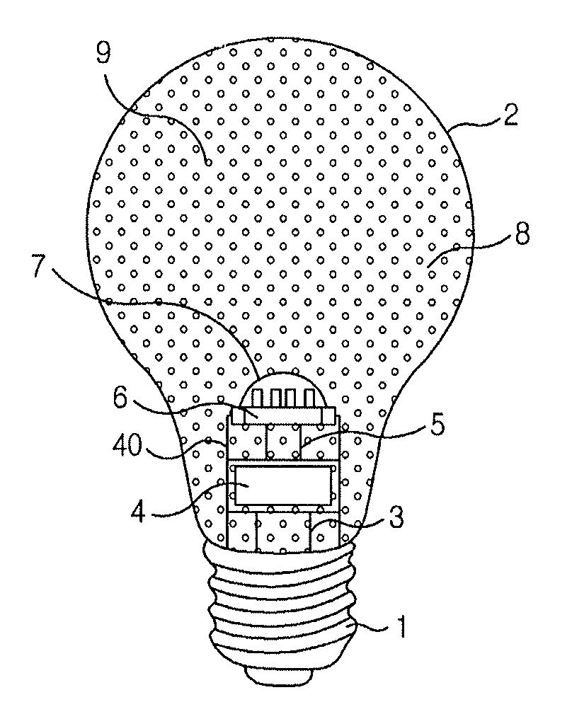
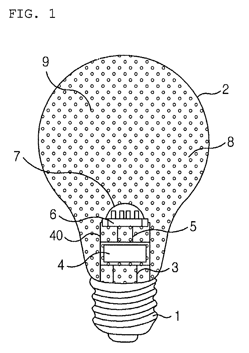
[0024]FIG. 1 is a perspective view showing a light emitting diode lamp according to an exemplary embodiment of the present invention. In FIG. 1, a direct current (DC) type LED lamp is shown.

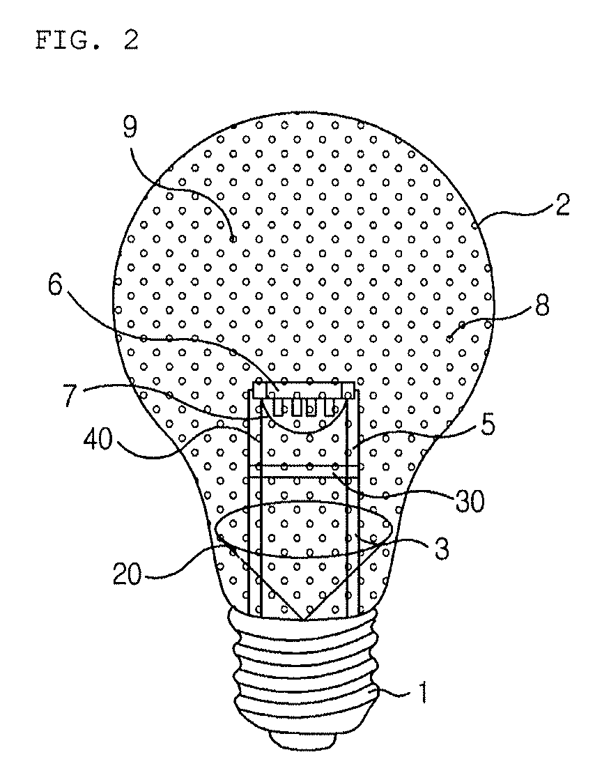
[0025]The LED lamp is configured to include a base 1, a housing 2, an alternating current (AC) power lead wire 3, a power supply module 4, a direct current (DC) power lead wire 5, a light emitting diode package 6, a lens 7, and a heat radiation liquid 9, as shown in FIG. 1.

[0026]The base 1 has a spiral protrusion structure capable of being...


PUM

PropertyMeasurementUnit
alternating currentaaaaaaaaaa
transparentaaaaaaaaaa
direct currentaaaaaaaaaa

Abstract

Disclosed herein is a a light emitting diode lamp including: a base having a power terminal capable of being electrically connected to an external alternating current (AC) power source; a housing coupled to the base and formed in a hollow structure; a light emitting diode package installed in the housing; the power supply module supplying an external AC power to the light emitting diode package; and a transparent insulating heat radiation liquid configured to radiate a heat generated from the light emitting diode package and the power supply module by impregnating the light emitting diode package and the power supply module therein and filled in the housing having the hollow structure.

Description

BACKGROUND OF THE INVENTION[0001]1. Technical Field[0002]The present invention relates to a light emitting diode lamp capable of having excellent light emitting efficiency and being manufactured at a low cost.[0003]2. Description of the Related Art[0004]As an electric bulb capable of generating brightness similar to that of an existing incandescent lamp at a low power, a light emitting diode (LED) incandescent lamp has been spotlighted.[0005]However, since the LED incandescent lamp used in various fields such as home illumination, office illumination, factory illumination, a streetlamp, a fishing lamp, scene illumination, illumination for leisure facilities is driven at a current and voltage different from those of the existing incandescent lamp, there is a problem that a power source facility including an electric bulb socket that has been already installed should be replaced. In addition, the LED incandescent lamp has a disadvantage in that it should effectively radiate a heat gen...

Claims


Application Information

Patent Timeline
Patent Type & Authority Patents(United States)
IPC IPC(8): F21V29/00F21K99/00F21V3/00F21V3/02F21V3/04F21V7/22F21V15/01F21V23/02F21V31/04F21Y101/02
CPCF21V29/30F21K9/135F21V31/04F21V15/01F21V23/02F21V29/508F21K9/50F21Y2101/02F21V7/22F21V3/02F21V3/0418F21V3/0436F21V3/0472F21V29/506F21V29/58F21K9/232F21K9/60F21Y2115/10F21V3/10F21V3/062F21V3/061F21V7/28
Inventor HAN, JANG-MINLIM, KYEONG-JUN
Owner G&C CO LTD
Learn More