
Powertrain and method for a kinetic hybrid vehicle

a technology of kinetic hybrid vehicles and powertrains, which is applied in the direction of electric propulsion mounting, transportation and packaging, gearing, etc., can solve the problems of reducing the potential fuel wasting the maximum efficiency potential of the engine, and reducing the efficiency of the vehicle, so as to achieve low energy conversion and conversion losses, the effect of improving fuel economy and reducing emissions

Active Publication Date: 2015-05-12
HE JING +1
View PDF42 Cites 12 Cited by
  • Summary
  • Abstract
  • Description
  • Claims
  • Application Information

AI Technical Summary

Benefits of technology

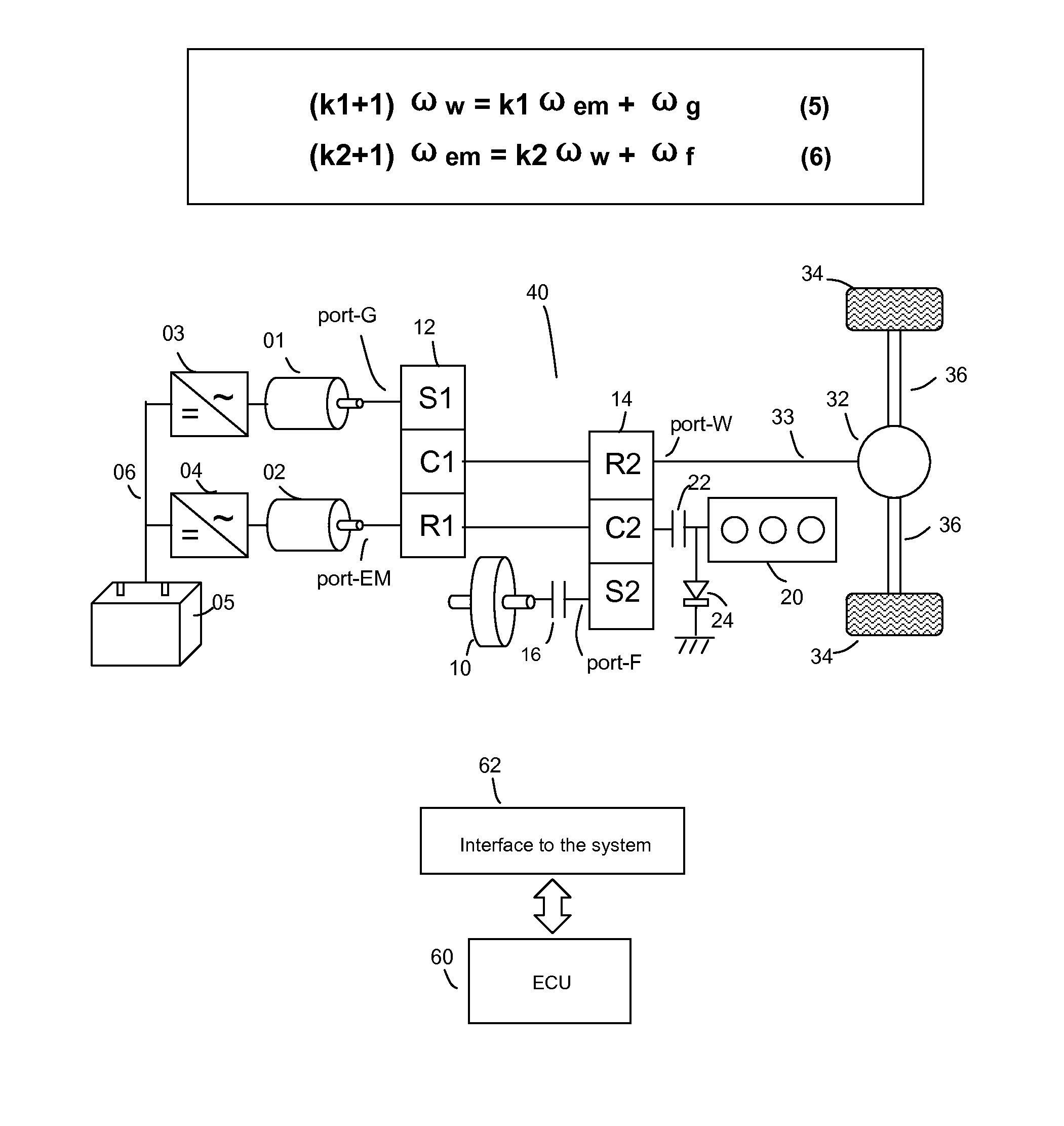
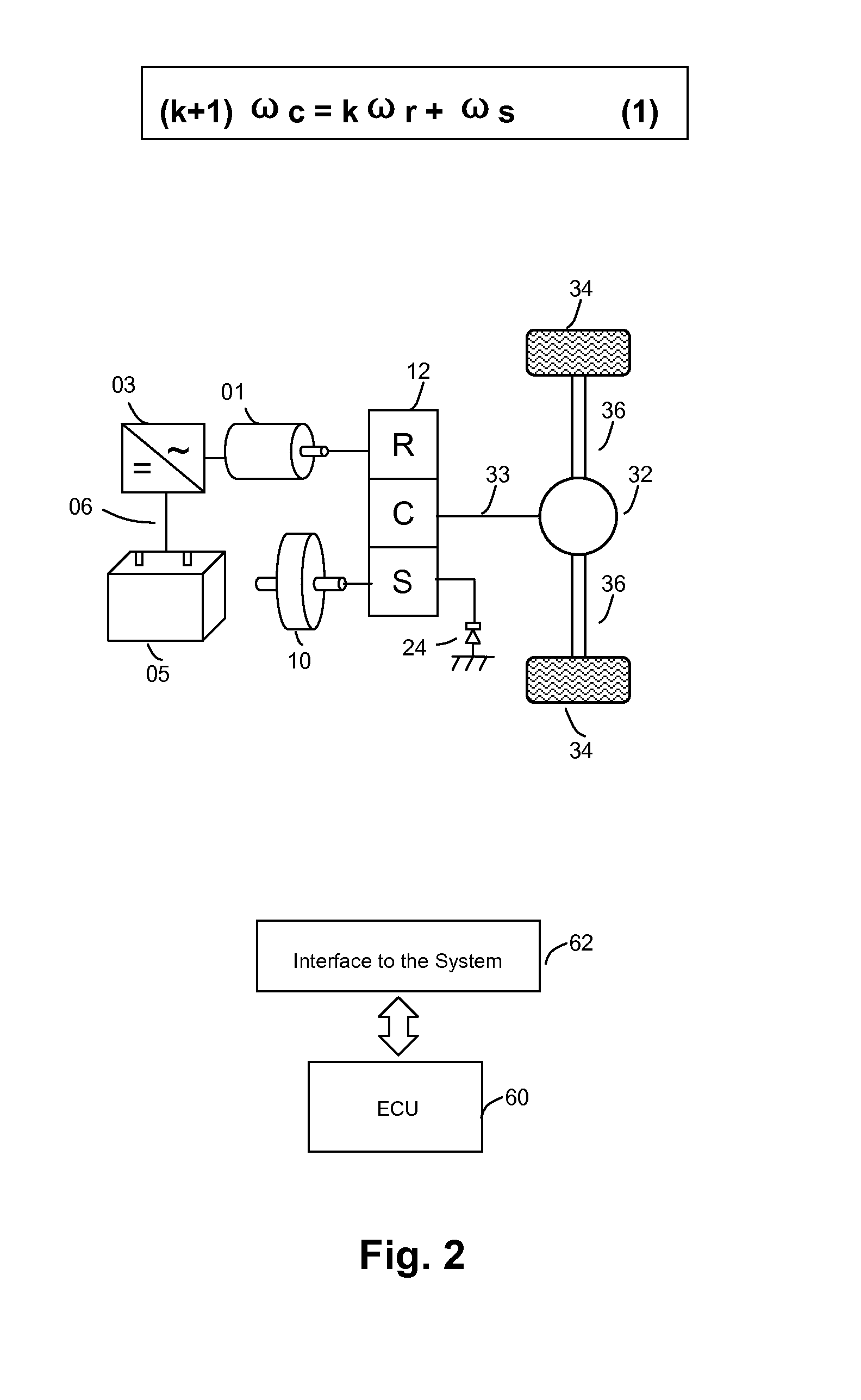
The present invention is a system that allows a vehicle to use a flywheel and an electrically controlled continuously variable transmission (CVT) to efficiently exchange energy with the vehicle. The flywheel can store and recover the vehicle's kinetic energy, and the CVT can change the speed ratio between the flywheel and the final drive to effectively transfer power to the vehicle's wheels across a range of vehicle speeds. The system also includes a method for controlling the powertrain to provide power to the vehicle during cruise with optimal efficiency. The invention allows for the engine to be run in a start-stop manner, minimizing conversion losses and optimizing efficiency. The vehicle can also be powered by a torque motor / generator or a combination of both, depending on the desired performance and range.

Problems solved by technology

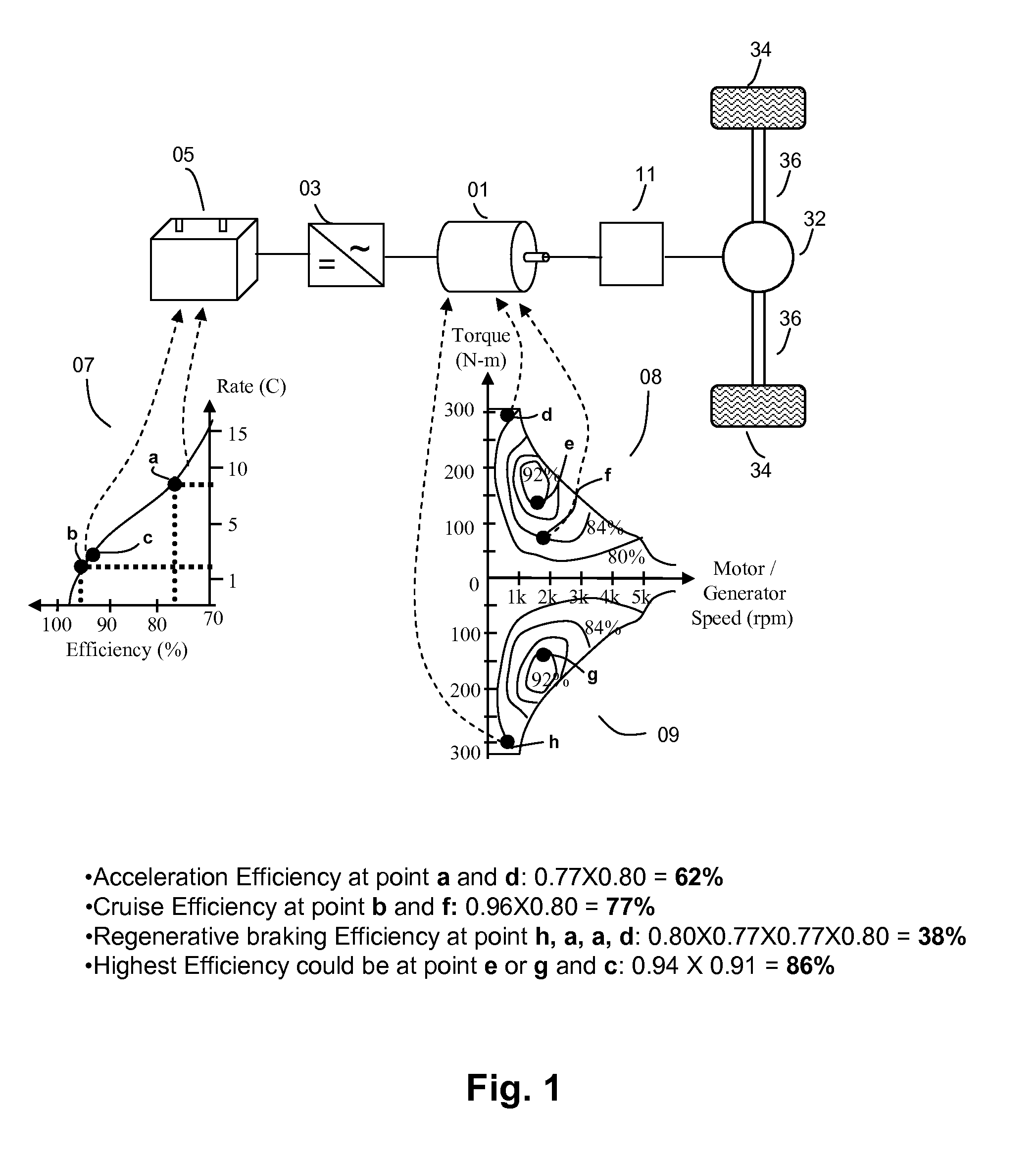
On the other hand, this means that when the vehicle is not accelerating, its engine is operating at a lower load level and lower efficiency state, wasting the maximum efficiency potential of the engine.
In addition, much of the vehicle's kinetic energy is dissipated as heat in the brakes when decelerating, reducing the vehicle's potential fuel efficiency.
Although more efficient and environment friendly than some conventional vehicles, these electric hybrids may be difficult to produce without the added costs of a large traction motor, controller, and electrochemical and / or electric storage devices.
These costs may result in an increased price to consumers that limits market penetration.
Aside from cost, a main disadvantage of electric hybrids is that they are greatly limited in the fuel economy improvements they can provide.
Part of conventional electric hybrids' efficiency limitations comes from the fact that energy is not stored in the same form it is used in.
There are typically four energy transformations by the time the energy is used, each resulting in a conversion loss.
These conversion losses typically comprise above one-third the original amount of energy initially recovered, such as from braking.
Another part of conventional electric hybrids' efficiency limitations comes from the inherent characteristics of motor / generators and batteries—namely, their power transfer limitations and reduced efficiency at high rates of charge and discharge.
Even when the electric storage consists of ultracapacitors, which are highly efficient at high rates of charge and discharge, the energy regenerated from deceleration is limited by the power of the traction motor.
In the early days of flywheel vehicle development and even now in some industrial applications and Uninterruptible Power Supply (UPS) systems, energy is stored into and released from the flywheel via one or more motor / generator(s), traveling a 100 percent electromagnetic path from source to destination; these flywheel systems also suffer multiple energy conversions and limited efficiency due to conversion losses.
Another disadvantage is that both systems may have critical points where the variator motor / generator approaches zero speed (stall state, maximum current) and the system has poor efficiency unless the effect is mitigated through other means such as by mechanically braking the variator port when the motor / generator approaches zero speed.

Method used


Image

  • Powertrain and method for a kinetic hybrid vehicle
  • Powertrain and method for a kinetic hybrid vehicle
  • Powertrain and method for a kinetic hybrid vehicle

Examples


Embodiment Construction

)

[0056]Embodiment(s) of the present invention are described herein with reference to the drawings. In the drawings, like reference numerals represent like elements.

Current Limitations of Electric Vehicle Propulsion Systems

[0057]Although both fuel efficiency and performance are desired in vehicles, they are conflicting goals in the design of a conventional vehicle powered by an internal combustion engine. High performance vehicles are equipped with large engines but suffer from poor efficiency, whereas fuel efficient vehicles lack performance.

[0058]Gas-electric hybrid vehicle technologies have made considerable advances in resolving the deadlock conflict between fuel efficiency and accelerative performance. These hybrid electric vehicles, or HEVs, rely on a downsized engine that works at a better efficiency converting fuel to mechanical power, while a motor, as a secondary mover, supplements power to compensate for a smaller engine's lack of reserve power for acceleration. In additio...


PUM


Abstract

A kinetic hybrid device and method for a vehicle may include a planetary gear system configured as a continuously variable transmission comprised of three or four ports. The kinetic hybrid device and method may include a flywheel connected to a first port of the system, a final drive connected to a second port of the system, and the variator for the flywheel connected to a third or fourth port of the system. The prime mover and / or other power sources may share a port with the flywheel, but do not share a port with the final drive.

Description

CROSS REFERENCE TO RELATED APPLICATION(S)[0001]This application claims priority from U.S. Provisional Patent Application Ser. Nos. 61 / 438,267 filed Feb. 1, 2011; 61 / 471,213, filed Apr. 4, 2011; and 61 / 495,993, filed Jun. 11, 2011, and which all are incorporated by reference herein.BACKGROUND OF THE INVENTION[0002]1. Field of the Invention[0003]This invention pertains to a powertrain and method of a kinetic hybrid vehicle, such as a gas and / or electric powered vehicle that includes a flywheel. The powertrain and method may be used to store and use energy of the flywheel device for vehicle propulsion.[0004]2. Description of the Related Art[0005]Improving fuel economy is an important objective in vehicle design, since it enables reduced fuel consumption and reduced emissions. In a conventional vehicle powered by an internal combustion engine, fuel economy is generally inversely related to vehicle performance, as the engine generally cannot be downsized to be run at its optimal efficien...

Claims


Application Information

Patent Timeline
Patent Type & Authority Patents(United States)
IPC IPC(8): F16H3/72B60K6/10B60K6/365B60K6/52F16H37/08
CPCB60K6/105B60K6/365B60K6/52Y02T10/6204F16H3/724F16H2037/088F16H2200/2005F16H2200/2007Y02T10/6265Y10T477/675Y10T477/23Y02T10/62
Inventor HE, JINGHE, HONGPING
Owner HE JING
Learn More