
Hybrid vehicle and control method for the same

a hybrid vehicle and control method technology, applied in the direction of machines/engines, process and machine control, instruments, etc., can solve the problems of driver or occupant discomfort, etc., to suppress sudden change in operation points.

Active Publication Date: 2015-04-28
TOYOTA JIDOSHA KK +1
View PDF17 Cites 3 Cited by
  • Summary
  • Abstract
  • Description
  • Claims
  • Application Information

AI Technical Summary

Benefits of technology

The invention provides a hybrid vehicle and a control method that can suppress a sudden change in the operation point of the internal combustion engine when the execution travel mode is switched while the engine is being operated. This is achieved by controlling the internal combustion engine and motor so that the charging / discharging electric power for charging or discharging the secondary battery is gradually changed and the vehicle travels in the switched execution travel mode. By doing so, it reduces the possibility of discomfort for the driver or occupant due to the sudden change in the operation point of the internal combustion engine.

Problems solved by technology

However, because the purposes of the travel modes are different from each other, the management of the charging / discharging of the secondary battery during the travel control in the electric-powered travel priority mode is different from the management of the charging / discharging of the secondary battery during the travel control in the hybrid travel priority mode.
Therefore, when the mode changeover switch is operated while the engine is being operated, an operation point for the engine may be suddenly changed due to a sudden change in the charging / discharging of the secondary battery, and thus, a driver or an occupant may feel discomfort.
Also, when the mode changeover switch is not operated but the travel mode is switched while the engine is being operated, the operation point for the engine may be suddenly changed, and thus, the driver or the occupant may feel discomfort.

Method used


Image

  • Hybrid vehicle and control method for the same
  • Hybrid vehicle and control method for the same
  • Hybrid vehicle and control method for the same

Examples


Embodiment Construction

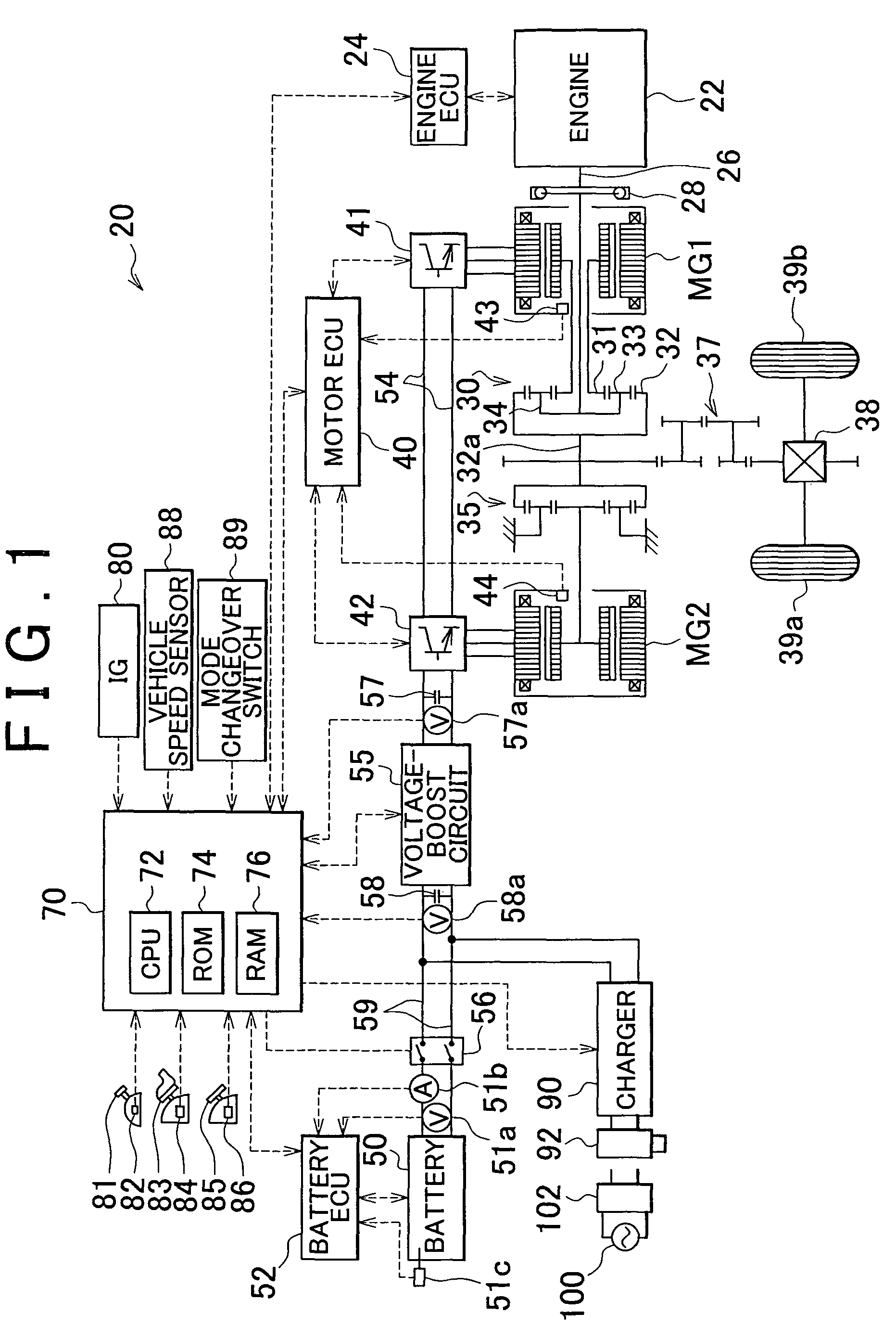
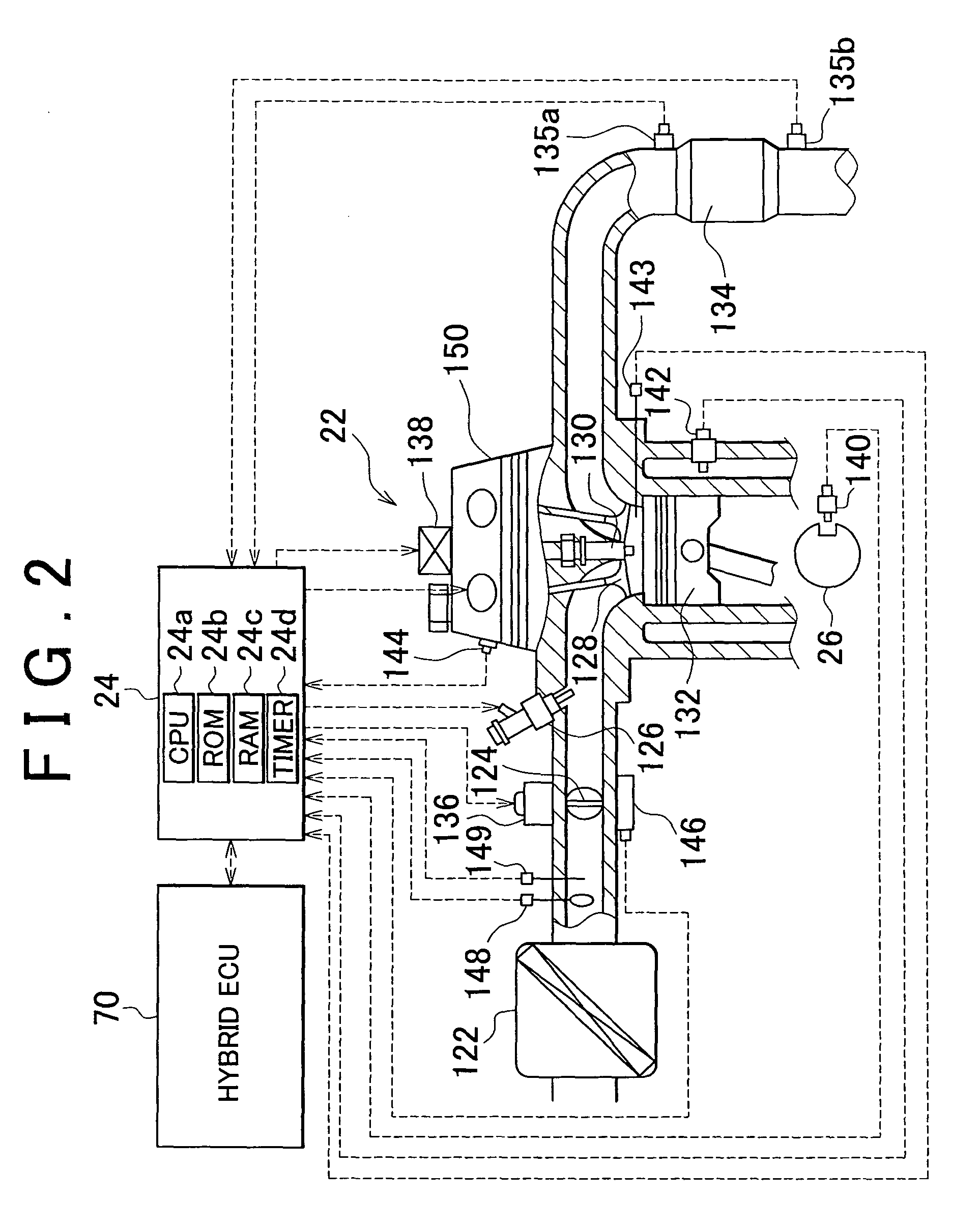
[0034]An embodiment of the invention will be described with reference to the drawings. FIG. 1 is a configuration diagram showing the schematic configuration of a hybrid vehicle 20 according to the embodiment of the invention. As shown in FIG. 1, the hybrid vehicle 20 according to the embodiment includes an engine 22, a three-axis power split / integration mechanism 30, a motor MG1, a motor MG2, inverters 41 and 42, a battery 50, a voltage-boost circuit 55, a system main relay 56, a charger 90, and a hybrid electronic control unit (hereinafter, referred to as “hybrid ECU”) 70. The engine 22 is configured as an internal combustion engine that outputs power using, for example, hydrocarbon fuel such as gasoline or light oil. The power split / integration mechanism 30 is configured as a planetary gear mechanism. In the power split / integration mechanism 30, a carrier 34 is coupled to a plurality of pinions 33, and is connected to a crankshaft 26 that is an output shaft of the engine 22 throug...


PUM


Abstract

A hybrid vehicle includes an internal combustion engine (22), a motor (MG2), and a secondary battery (50), and travels in an electric-powered travel mode and in a hybrid travel mode. In the hybrid vehicle, an execution travel mode is set to one of two travel modes including an electric-powered travel priority mode where the hybrid vehicle travels with priority being given to the electric-powered travel mode over the hybrid travel mode, and a hybrid travel priority mode where the hybrid vehicle travels with priority being given to the hybrid travel mode over the electric-powered travel mode. When the execution travel mode is switched while the internal combustion engine (22) is being operated, the internal combustion engine (22) and the motor (MG2) are controlled so that charging / discharging electric power for charging or discharging the secondary battery (50) is gradually changed and the hybrid vehicle travels in the switched execution travel mode (S750 to S800).

Description

BACKGROUND OF THE INVENTION[0001]1. Field of the Invention[0002]The invention relates to a hybrid vehicle and a control method for the same. More specifically, the invention relates to a hybrid vehicle that travels using only power input to and output from a motor in an electric-powered travel mode, and travels using power output from an internal combustion engine and the power input to and output from the motor in a hybrid travel mode, and a control method for the same.[0003]2. Description of Related Art[0004]Japanese Patent Application Publication No. 2007-62640 (JP-A-2007-62640) describes an example of the hybrid vehicle. In the publication No. 2007-62640, when a target state of charge (SOC), which is the target state of charge of a secondary battery, is set, the hybrid vehicle travels in an HV mode where only power from a motor is used and an engine is stopped until the state of charge (SOC) of the secondary battery reaches the target SOC. After the SOC of the secondary battery ...

Claims


Application Information

Patent Timeline
Patent Type & Authority Patents(United States)
IPC IPC(8): B60W20/00B60K6/44B60K6/445B60K6/448B60K6/52B60K6/54B60L50/16B60W10/06B60W10/08B60W10/26B60W30/182B60W30/188B60W50/00B60W50/08F02D29/02
CPCB60W20/10B60K6/445B60W10/06B60W10/08B60W10/26B60W20/102B60W30/182B60W30/188B60W50/082B60W20/20B60L2240/486B60W2050/0066B60W2510/244B60W2540/04B60W2540/10B60W2710/105B60W2710/1061Y02T10/6239Y02T10/6269Y02T10/6286Y10S903/93B60W20/11B60W2540/215Y02T10/62B60W50/085
Inventor YAMAMOTO, MASAYAFUNADA, MASASHI
Owner TOYOTA JIDOSHA KK
Learn More