
Semiconductive roller

a technology of semi-conductive rollers and conductive plates, applied in the direction of shafts and bearings, instruments, thin material processing, etc., can solve the problems of reducing image durability, insufficient effect, and easy deterioration of toner, and achieve excellent image durability, high quantity of toner charge, and hardly reducing image density

Inactive Publication Date: 2015-04-21
SUMITOMO RUBBER IND LTD
View PDF16 Cites 7 Cited by
  • Summary
  • Abstract
  • Description
  • Claims
  • Application Information

AI Technical Summary

Benefits of technology

The solution effectively suppresses toner adhesion and maintains high image quality and durability by optimizing the compounding ratio of rubber components and adding an oxide film, ensuring stable roller resistance and extended product life with reduced manufacturing complexity and cost.

Problems solved by technology

However, the effect is not sufficiently attained by merely blending the filler in a small quantity.
If the compounding ratio of the filler is increased up to a range for sufficiently attaining the effect, on the other hand, the hardness of the roller body is increased to cause another problem.
In other words, the toner is easily deteriorated to reduce image durability, or a nip width is reduced when the roller body is brought into pressure contact with the surface of the photosensitive body, to lower the quality of the formed image.
When the image durability is reduced, fogging is easily caused in the formed image.
The fogging is such a phenomenon that the deteriorated toner spreads also on margins of the formed image to reduce the quality of the image.

Method used


Image

  • Semiconductive roller
  • Semiconductive roller

Examples


example 1

[0179](Preparation of Rubber Composition)

[0180]80 parts by mass of SBR [JSR 1502 by JSR Corporation] and 20 parts by mass of GECO [Epion (registered trademark) ON301 by Daiso Co., Ltd., EO / EP / AGE=73 / 23 / 4 (molar ratio)] were blended as rubber components. The compounding ratio of the SBR with respect to 100 parts by mass of the total quantity of the rubber components was 80 parts by mass.

[0181]A rubber composition was prepared by masticating 100 parts by mass of the total quantity of the rubber components in a Banbury mixer, kneading the mixture while adding components shown in Table 1 except a crosslinking component, and further kneading the mixture while finally adding the crosslinking component.

[0182]

TABLE 1ComponentPart by MassSulfur-Based Crosslinking Agent0.75Thiourea0.85Accelerator DM0.5Accelerator TS1Accelerator DT0.8Conductive Filler5Acid Acceptor3

[0183]The components shown in Table 1 are as follows:

[0184]Sulfur-based crosslinking agent: powdered sulfur

[0185]Thiourea: ethylen...

example 2

[0197]A semiconductive roller was manufactured by preparing a rubber composition similarly to Example 1, except that 70 parts by mass of the SBR, 20 parts by mass of GECO and 10 parts by mass of CR [Shoprene (registered trademark) WRT by Showa Denko K. K.] were blended as rubber components. The compounding ratio of the SBR with respect to 100 parts by mass of the total quantity of the rubber components was 70 parts by mass.

example 3

[0198]A semiconductive roller was manufactured by preparing a rubber composition similarly to Example 2, except that the quantities of the SBR and the CR were changed to 50 parts by mass and 30 parts by mass respectively. The compounding ratio of the SBR with respect to 100 parts by mass of the total quantity of the rubber components was 50 parts by mass.


PUM


Abstract

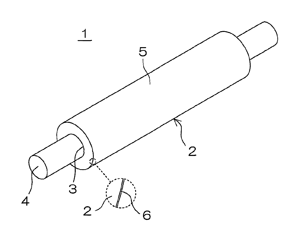
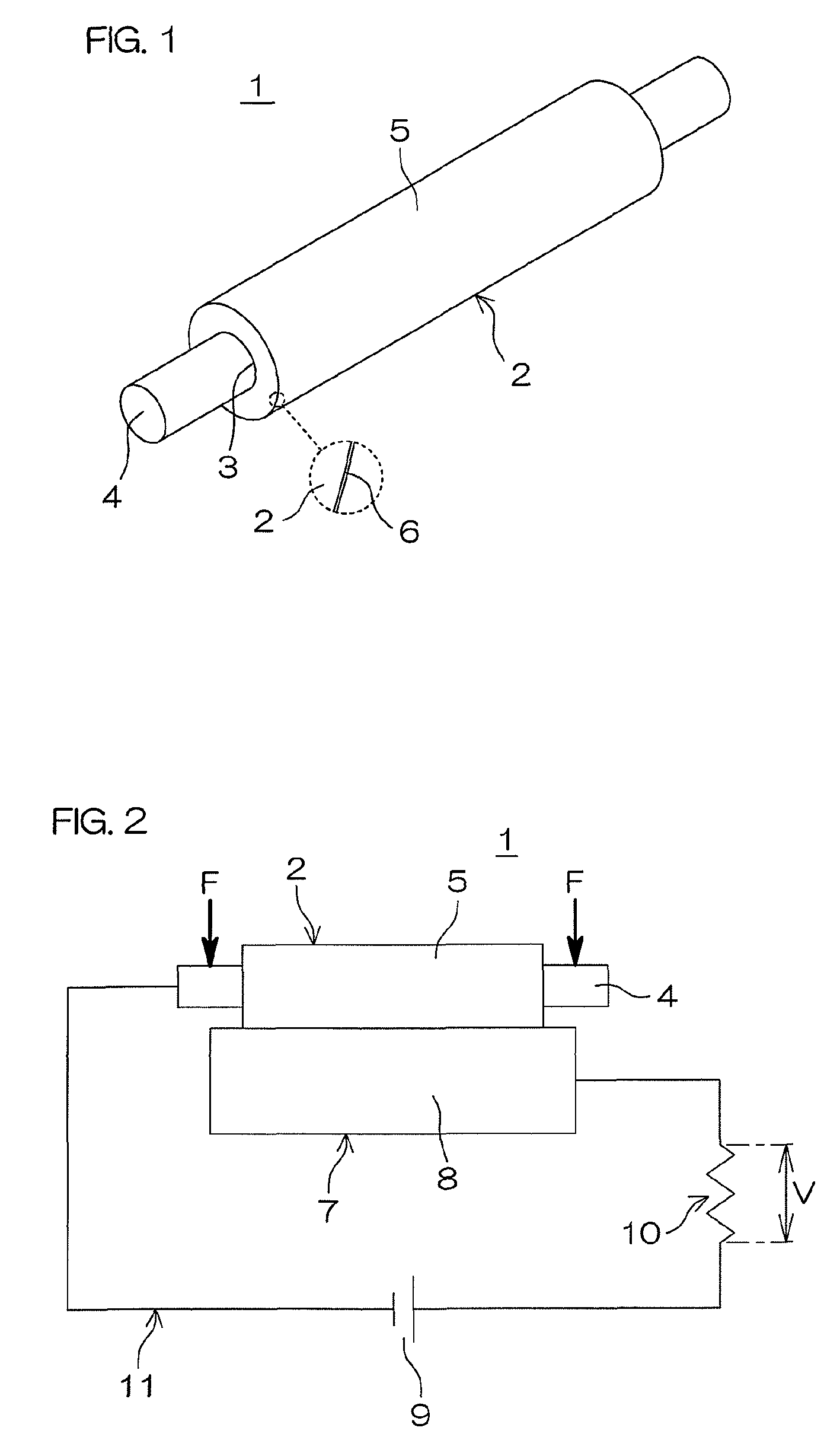
The semiconductive roller according to the present invention includes a nonporous roller body made of a rubber composition containing styrene-butadiene rubber and epichlorohydrin rubber as rubber components.

Description

BACKGROUND OF THE INVENTION[0001]1. Field of the Invention[0002]The present invention relates to a semiconductive roller suitably employable as a developing roller or a charging roller in an image forming apparatus, such as a laser printer, an electrostatic copier, a plain paper facsimile or a composite machine thereof, for example, utilizing electrophotography.[0003]2. Description of Related Art[0004]Various types of image forming apparatuses utilizing electrophotography are increasingly improved, in order to satisfy requirements for speed increase, improvement in picture quality, colorization and downsizing.[0005]The key to such improvements is toner. In other words, refinement of the toner, uniformization of the particle diameter of the toner, and sphericalization of the toner shape are necessary, in order to satisfy the requirements.[0006]As to the refinement of the toner, fine toner having an average particle diameter of not more than 10 μm or not more than 5 μm has been develo...

Claims


Application Information

Patent Timeline
Patent Type & Authority Patents(United States)
IPC IPC(8): F16C13/00G03G15/08
CPCG03G15/0818Y10T428/31931G03G15/06
Inventor MIZUMOTO, YOSHIHISAMARUI, TAKASHI
Owner SUMITOMO RUBBER IND LTD
Learn More