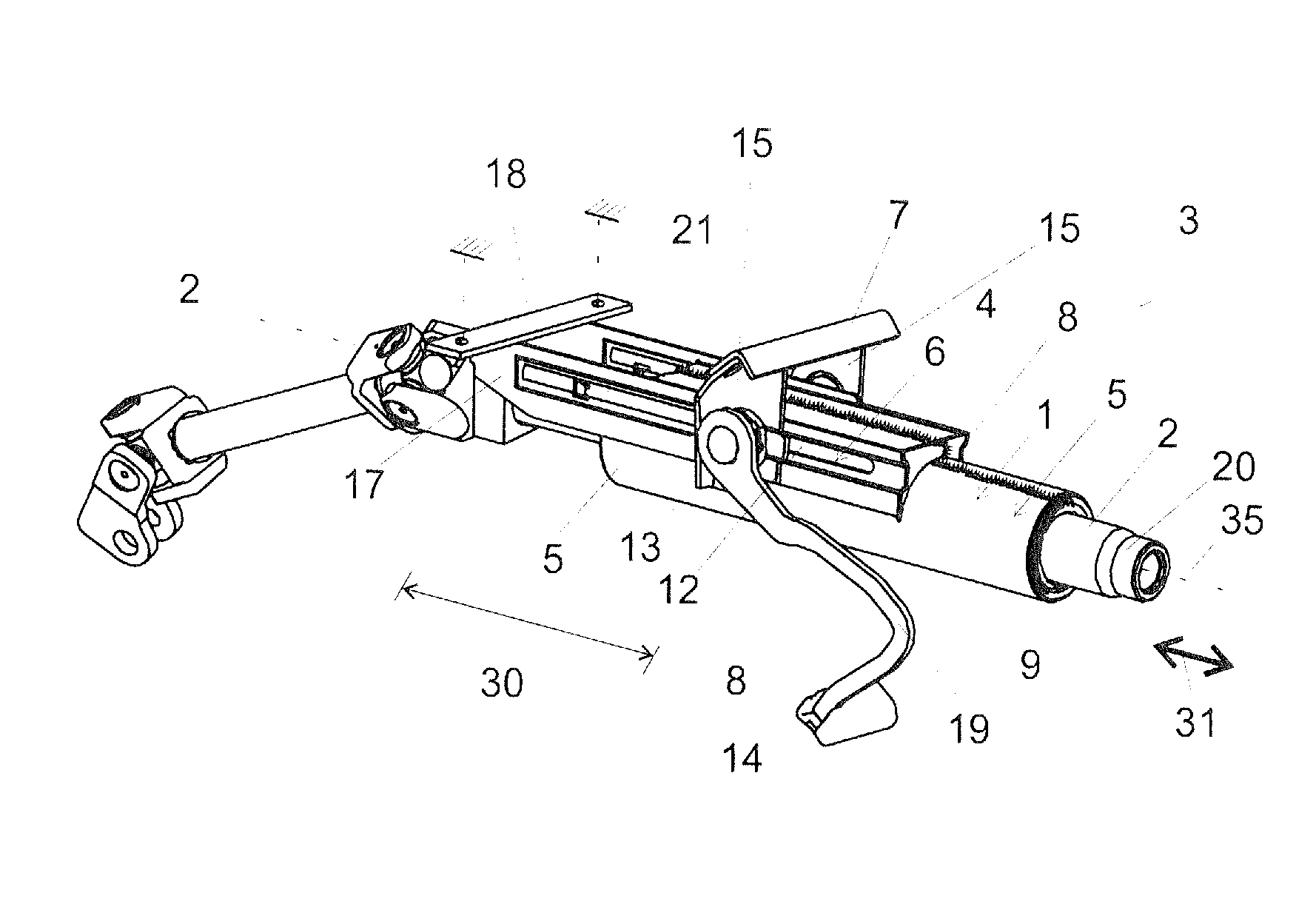
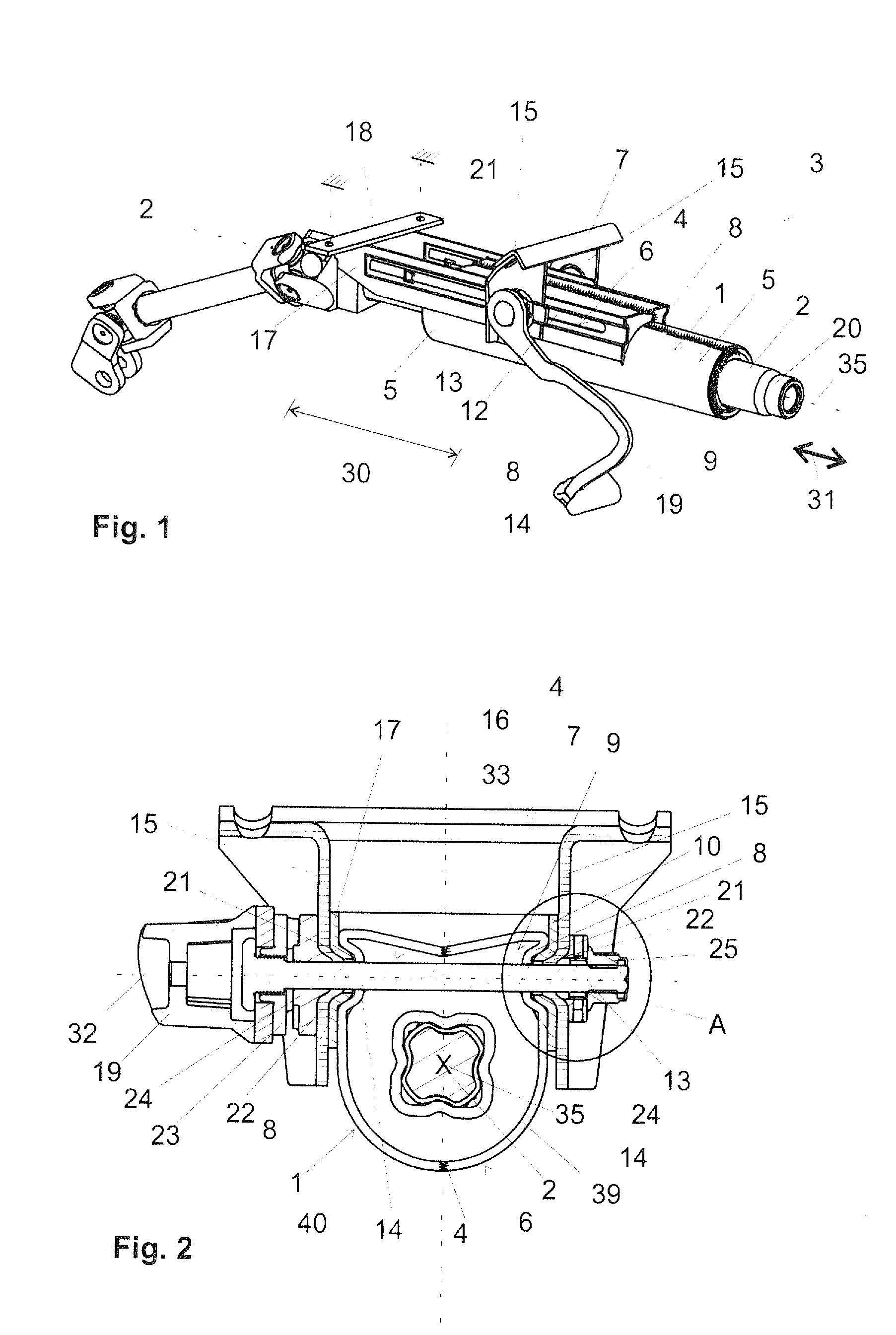
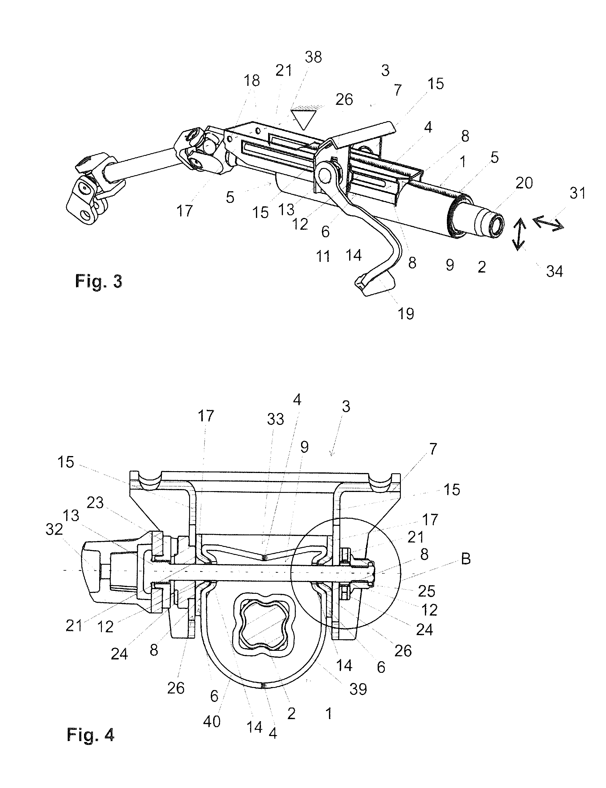
[0007]Through the initially separate fabrication of these half shells, it is possible to produce the half shells quickly and cost-effectively. The joining, in particular by welding, can also be carried out simply and cost-effectively. The steering shaft bearing unit can thereby be produced highly economically. With this approach it is moreover not problematic to meet the required demands made of rigidity. The individual half shells or their subhalf shells or component parts from which they are produced by joining can be formed, in case they are produced by means of sheet metal reforming, at low reforming degrees such that good strength and low wall thickness reduction can be achieved in the securement region also.
[0017]To increase the rigidity of the steering shaft bearing unit in particular in the region of the securement webs, in the steering shaft bearing unit at least one steering shaft bearing unit bead can be disposed. The, preferably each, through-opening can preferably in each case be disposed in a steering shaft bearing unit bead. Especially preferred embodiments of the invention provide in this context that the steering shaft bearing unit comprises precisely two steering shaft bearing unit beads and that in each steering shaft bearing unit bead is disposed one through-opening for guiding through a clamp bolt known per se. Each securement web advantageously comprises precisely one steering shaft bearing unit bead in each of which one through-opening is disposed. The steering shaft bearing unit beads are advantageously disposed in the proximity of end regions of the securement webs. The through-openings are preferably elongated holes. It is furthermore advantageous for the through-opening to be disposed in the bead base of the steering shaft bearing unit bead. It is especially advantageous for the through-opening to be disposed approximately symmetrically between the side walls or margins delimiting the bead base and extending approximately parallel.
[0024]The steering column according to the invention can advantageously be implemented such that it can be set in its height, which is identical to inclination, and / or in its length. Preferred are generally cost-effective height- and length-adjustable steering columns which comprise a securement device that makes possible the optional enabling (=open state of the securement device) or fixing (=closed state of the securement device) of the particular displacement direction. The clamp bolt, as a part of such a securement device, together with further clamping parts, such as for example a tightening member, a cam plate, a clamping nut, can herein serve in simple manner for the optional enabling or fixing of the feasible adjustment in length directions and / or height direction in known manner, depending on the realization. Independently of fixing under form closure or force closure (also friction closure), it is always advantageous for high pressing forces to be applied in the closed state of the securement device onto the connections between steering shaft bearing unit and bearing part, on the one hand, and bearing part and bracket part, on the other hand.
[0025]Through the penetration of the clamp bolt through steering shaft bearing unit bead and bearing part bead, the tightening forces exerted by the clamp bolt are directly transmitted to the two listed beads, such that using a simple construction high forces can be transmitted. This aids also in reducing the number of structural parts. In the open state, in which no or only minimal tightening forces are transmitted via the clamp bolt, high guide precision in the adjustment is also attained. The rigidity can herein be further increased if the bearing part and the steering shaft bearing unit on the surfaces oriented parallel to the two side jaws comprise on both sides of the steering shaft correspondingly one steering shaft bearing unit bead and one bearing part bead, which are penetrated by a clamp bolt. This also aids in reducing the number of structural parts and / or the material utilization for the production of the steering column. In the open state, in which no or only minimal tightening forces are transmitted via the clamp bolt, through the assembly according to the invention a low-play guide system is attained without large expenditures. To the driver of the motor vehicle, consequently, in this state also a stable and full sensation is conveyed when handling the steering wheel attached on the steering shaft of the steering column. The bearing part bead and the steering shaft bearing unit bead as well as a bracket part bead optionally also provided and discussed below, are advantageously developed such that they correspond to one another. It is in these terms also preferred if the bearing part bead is developed, viewed in a section plane through a longitudinal center axis of the clamp bolt, geometrically similar to the steering shaft bearing unit bead. The same applies advantageously also to a bracket part if such is provided. It is further also advantageous if the bearing part bead and / or the steering shaft bearing unit bead and / or the optionally provided bracket part bead is or are developed axisymmetrically with respect to a longitudinal center axis of the clamp bolt.
[0029]By guiding the clamp bolt through the bearing part bead, the steering shaft bearing unit bead and optionally also the bracket part bead, a highly compact construction method can be achieved. The clamp bolt can be disposed in close proximity on the steering shaft rotatably bearing supported in the steering shaft bearing unit. This leads to an equally compact as well as also stable construction method. In addition, the forces transmitted via the clamp bolt act very directly onto said beads.
[0030]It is advantageously provided that the bolt penetrates centrally the bearing part bead and the steering shaft bearing unit bead as well as the optionally provided bracket part bead which is further advantageous for a symmetric force introduction distributed onto all side walls of the particular beads. The bead base advantageously has a width such that the clamp bolt can be guided completely through an opening in the bead base. The bead base can still comprise further regions lateral to the openings, with which regions it is braced on the bead bases of the other beads. The openings or cutouts in the beads or bead bases through which the clamp bolt is guided should advantageously be greater than the diameter of the clamp bolt such that the clamp bolt is not in direct contact on the margins of the openings or cutouts. This has, for example, the advantage that in the event of a motor vehicle crash, no rotational movement of the clamp bolt is triggered. Moreover, the abrasion in the elongated holes is reduced.


