
Lighting devices comprising an array of optoelectronic sources

a technology of optoelectronic sources and lighting devices, which is applied in the direction of route marking with anchoring lightships, outdoor lighting, traffic control systems, etc., can solve the problems of high energy consumption and maintenance costs of traditional incandescent sources, and it is not easy or feasible to use optoelectronic sources

Inactive Publication Date: 2015-04-14
CONSIGLIO NAT DELLE RICERCHE
View PDF44 Cites 5 Cited by
  • Summary
  • Abstract
  • Description
  • Claims
  • Application Information

AI Technical Summary

Benefits of technology

The present invention provides lighting devices with an array of premium lighting sources that offer an alternative to traditional incandescent sources. These lighting devices have a more uniform and consistent light output, resulting in better energy efficiency and more precise color control. Overall, the patent text describes a new technology for generating lighting with improved performance and efficiency.

Problems solved by technology

Since optoelectronic sources are spatially distributed in the array, in some cases it is not easy or feasible to use optoelectronic sources.
Traditional incandescence sources, however, have high energy consumption and maintenance costs.

Method used


Image

  • Lighting devices comprising an array of optoelectronic sources
  • Lighting devices comprising an array of optoelectronic sources
  • Lighting devices comprising an array of optoelectronic sources

Examples


Embodiment Construction

[0012]In the appended Figures, similar or like elements will be designated by the same numeral references.

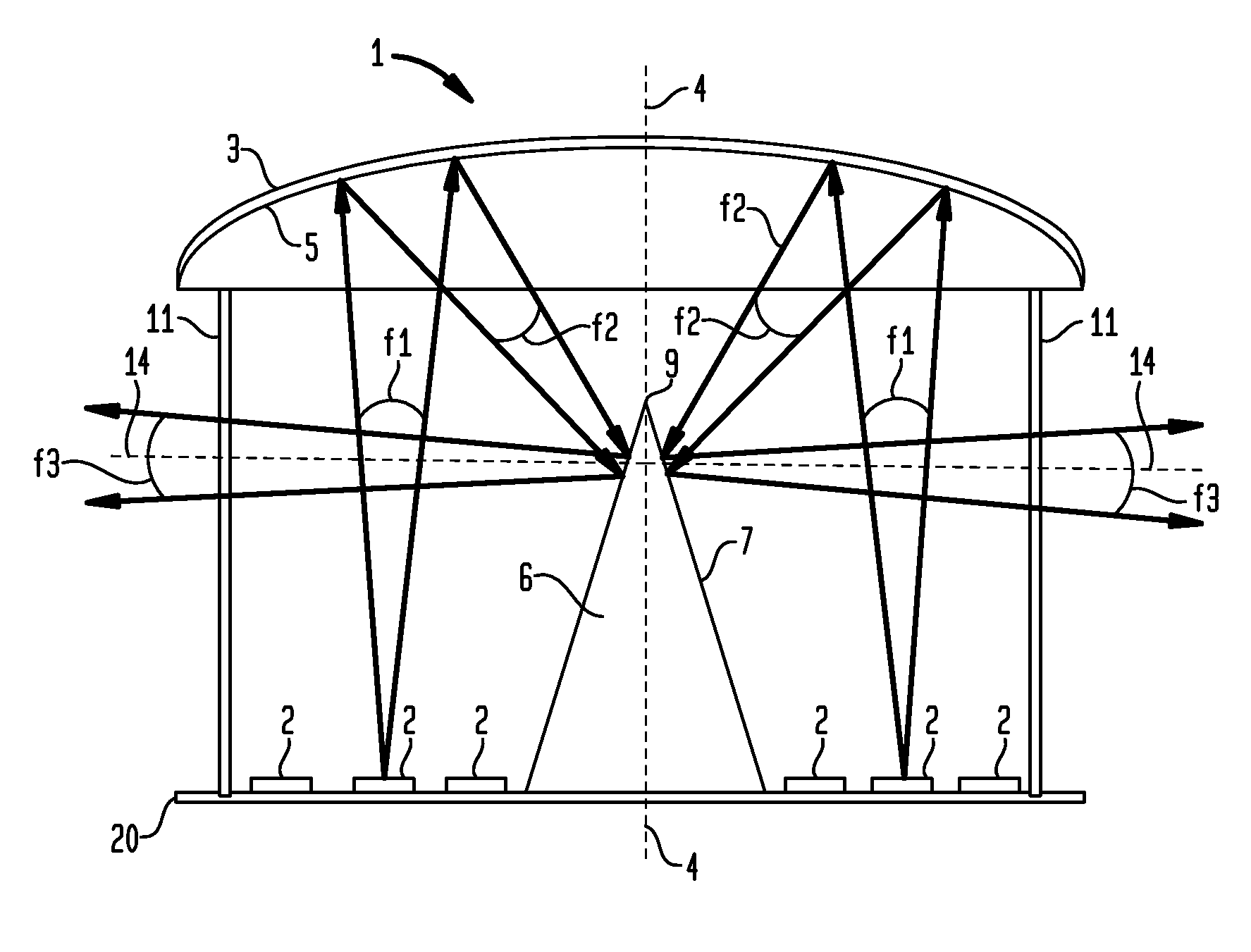
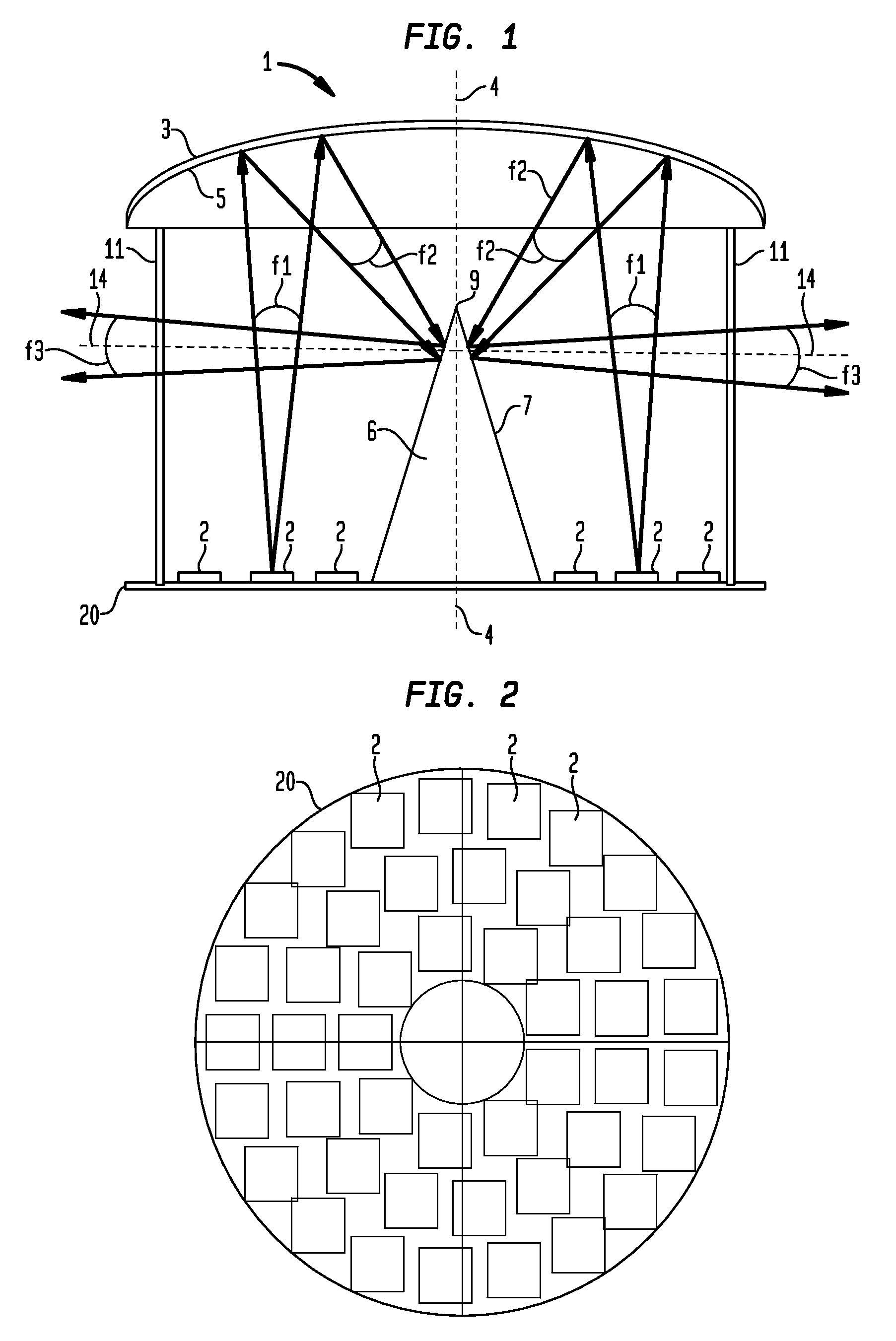
[0013]In FIG. 1, a lighting device is shown which includes an array of spatially distributed optoelectronic sources 2. In accordance with a non-limiting embodiment, the lighting device 1 may be part of a maritime signaling marker light, or lighthouse lamp or lamps for maritime signalling. In accordance with an alternative embodiment, the above-mentioned device may be a lighting device for internal environments, for example, domestic environments. In accordance with possible further embodiments, the above-mentioned device may be an external lighting device of a vehicle, such as a camping lamp or a lighting device for public or private external spaces.

[0014]In certain embodiments, the optoelectronic sources 2 may be LED sources, i.e., where each of them includes a LED diode. In other alternative embodiments, such sources may be LASER sources, i.e., each of them includes a laser di...


PUM

PropertyMeasurementUnit
opening angleaaaaaaaaaa
outer diameteraaaaaaaaaa

Abstract

Lighting devices are provided including those which have an array of spatially distributed optoelectronic sources, each source being adapted to emit a respective incident optical beam; a first reflector having an optical axis, and having a first reflective surface that is concave and facing the array of sources to intercept said incident optical beams and to produce corresponding reflected optical beams; a second reflector having a second reflective surface interposed along said optical axis between said array of optoelectronic sources and the first reflector adapted to intercept and deflect said reflected optical beams producing corresponding deflected optical beams, the first reflector being adapted to concentrate the reflected optical beams on the second reflective surface.

Description

CROSS REFERENCE TO RELATED APPLICATION[0001]This application claims priority to and benefit of Italian Patent Application No. RM2012A000265 filed Jun. 7, 2012, the contents of which are incorporated by reference in their entirety.FIELD OF THE INVENTION[0002]The present invention relates to the technical field of lighting devices, and in particular, to lighting devices which include an array of optoelectronic sources.BACKGROUND OF THE INVENTION[0003]In the technical field of lighting devices, optoelectronic sources such as LED sources to a greater extent, and laser sources to a lesser extent, are becoming more widely used to replace traditional incandescence sources. This involves advantages in terms of energy consumption and maintenance costs. In fact, the optoelectronic sources have lower power consumption than those of incandescence lamps, and they have a service life that is longer than incandescence lamps.[0004]Generally, due to emitted optical power needs, in order to replace a...

Claims


Application Information

Patent Timeline
Patent Type & Authority Patents(United States)
IPC IPC(8): G08G3/00B60Q1/00F21V1/00B63B51/02F21K99/00F21S8/10F21V7/00F21V7/04F21V7/06F21V7/07F21V7/08F21V7/22F21W111/043F21W131/10F21Y101/02F21Y105/00H05B44/00
CPCF21V7/00F21S48/23F21V7/0033F21V7/041H05B33/0803B63B51/02F21V7/045G08G3/00F21S48/215F21K9/00F21V7/06F21V7/07F21V7/08F21V7/22F21W2111/043F21W2131/10F21Y2101/02F21Y2101/025F21Y2105/003F21Y2105/12F21Y2105/10F21Y2115/30F21Y2115/10F21K9/68F21S43/14F21S43/30H05B45/00F21V7/28F21V7/24
Inventor JAFRANCESCO, DAVIDMERCATELLI, LUCASANSONI, PAOLAFONTANI, DANIELASANI, ELISAFRANCINI, FRANCO
Owner CONSIGLIO NAT DELLE RICERCHE
Learn More