
Providing phase diversity combining of digital radio broadcast signals

a digital radio and phase diversity technology, applied in the field of providing phase diversity combining of digital radio broadcast signals, can solve the problems of increased bit error rate, long multipath delay (or frequency selective fading), deep fade of wideband, etc., and achieve the effect of greater weigh

Active Publication Date: 2015-04-07
SKYWORKS SOLUTIONS INC
View PDF33 Cites 8 Cited by
  • Summary
  • Abstract
  • Description
  • Claims
  • Application Information

AI Technical Summary

Benefits of technology

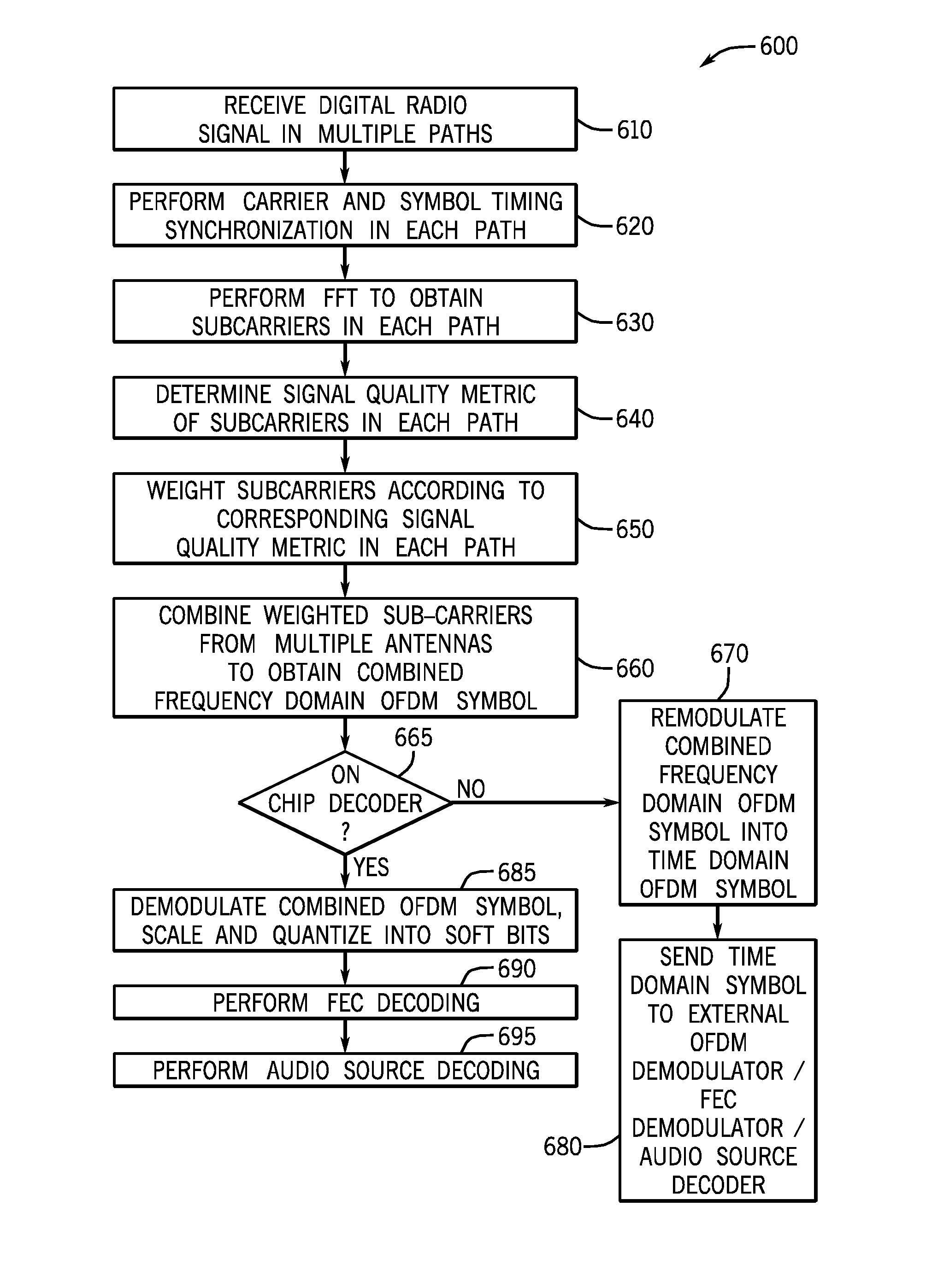
This patent is about a way to combine radio signals to improve signal quality. The method involves comparing the quality of two signals and giving more weight to the signal with the higher quality. This way, the signals can be combined to create a better signal. In some cases, the signals can be combined at different frequencies to make them even better.

Problems solved by technology

Multipath distortion is caused when two or more radio signals modulating the same message signal arrive at a receiver at different times and with different phases and attenuation levels due to reflections of the signal from various objects.
In urban environments, reflections from close-in objects such as buildings result in short delay multi-path fading, causing wideband deep fades.
In turn, long multipath delay (or frequency selective fading) arises due to reflections from objects several kilometers away such as distant hills and tall buildings.
Multipath impairments on a digital radio signal result in increased bit error rates at the demodulator output and may result in audio distortion and or partial loss of data services.
Although antenna phase diversity for analog FM broadcast signals is known and implemented in certain vehicle platforms, current architectures cannot handle digital radio broadcasts (for example HD™ radio or Digital Audio Broadcasting (DAB)).

Method used


Image

  • Providing phase diversity combining of digital radio broadcast signals
  • Providing phase diversity combining of digital radio broadcast signals
  • Providing phase diversity combining of digital radio broadcast signals

Examples


Embodiment Construction

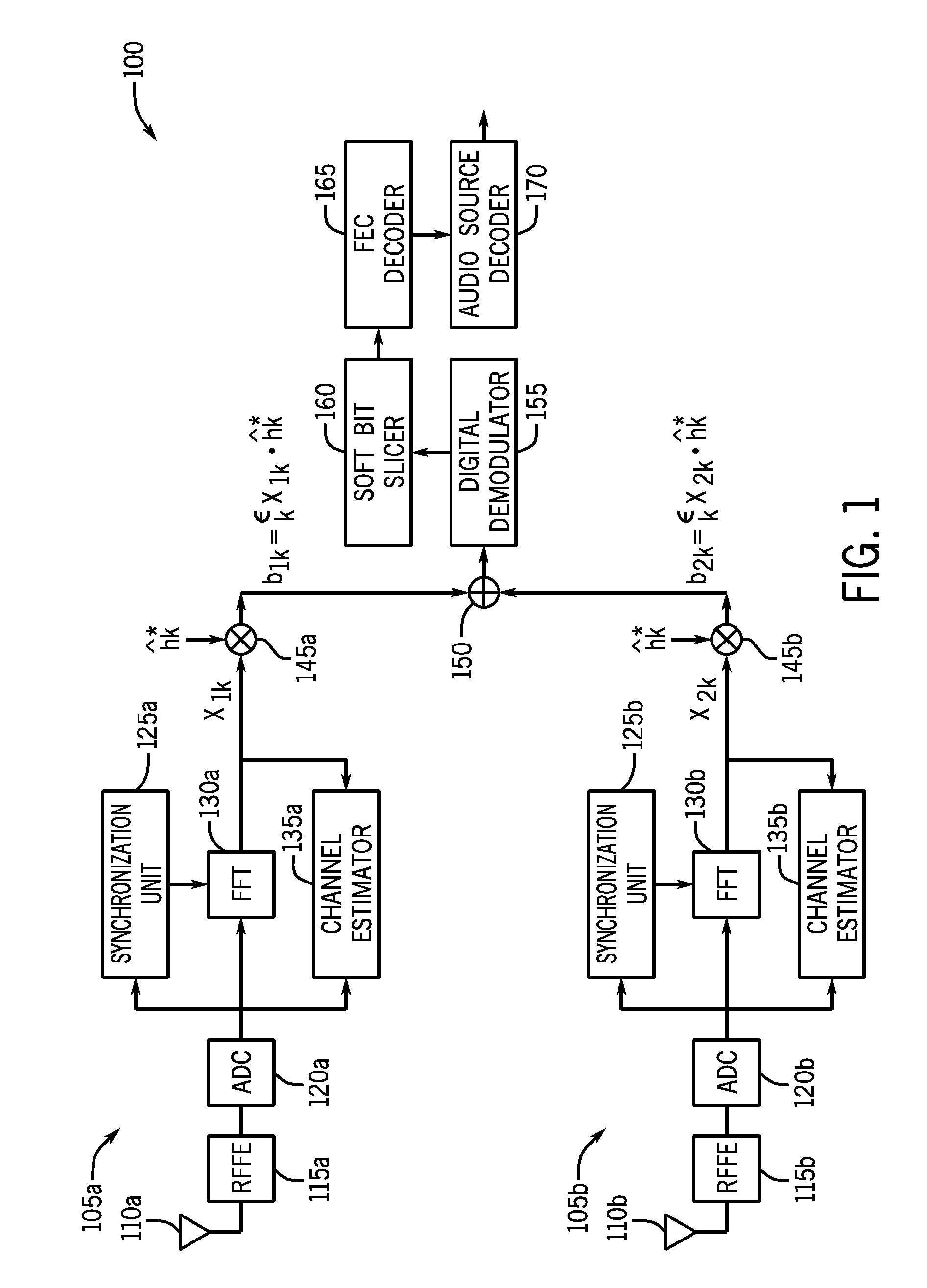
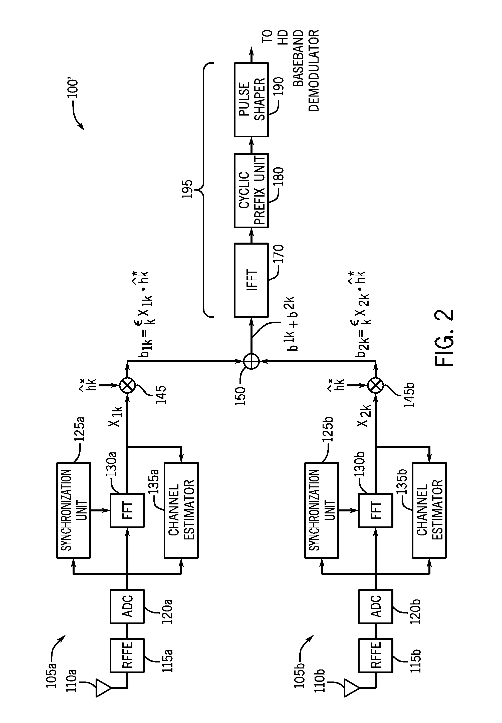
[0017]Embodiments may provide for a multi-tuner phase diversity scheme for reception of digital broadcast radio signals, such as transmitted according to an orthogonal frequency division multiplexing (OFDM) scheme. After receipt in the given tuner from an associated antenna, the radio frequency (RF) signal may be downconverted. In turn, a digitized signal from each tuner is coherently combined in the frequency domain to obtain a combined digital signal that may then be provided to a digital demodulator and forward error correction (FEC) decoder. The signals from the multiple antennas may be combined in a predetermined manner based on relative quality metrics associated with each signal to produce a combined signal that is more robust to multipath fading.

[0018]Implementations may vary. However, certain implementations may be used for automotive radios. In such an automotive system, multiple antennas may be provided, with the output of each antenna provided to a separate and independe...


PUM


Abstract

In one embodiment, a method for performing antenna diversity combining for digitally broadcast radio signals includes generating a first signal quality metric for a first signal obtained from an incoming digitally broadcast radio signal received in a first signal path, and similarly generating a second signal quality metric for a second signal obtained from the radio signal received in a second signal path. Then the first and second signals from these paths can be coherently combined based on the signal quality metrics to obtain a combined frequency domain symbol. In some embodiments, this combined frequency domain symbol may be remodulated to a time domain symbol. Also in some embodiments N tuners can be daisy chained to generate a final output that is either a frequency domain symbol of combined sub-carriers, soft bits to a forward error correction (FEC) decoder, or a remodulated time domain symbol. As a further possibility, each of the N tuners can use a different local oscillator (LO) frequency.

Description

BACKGROUND[0001]Multipath distortion is caused when two or more radio signals modulating the same message signal arrive at a receiver at different times and with different phases and attenuation levels due to reflections of the signal from various objects. The radio signal, prior to arriving at the receiver, can experience changes in amplitude and phase due to two types of multipath fading: flat and frequency-selective. In urban environments, reflections from close-in objects such as buildings result in short delay multi-path fading, causing wideband deep fades. In this scenario all spectral components of the signal experience amplitude attenuation simultaneously (flat fading). In turn, long multipath delay (or frequency selective fading) arises due to reflections from objects several kilometers away such as distant hills and tall buildings. In this case subsets of sub-carriers in the signal are impaired. Multipath impairments on a digital radio signal result in increased bit error ...

Claims


Application Information

Patent Timeline
Patent Type & Authority Patents(United States)
IPC IPC(8): H04B7/10H04L1/02H04B7/08
CPCH04B7/0845
Inventor ELENES, JAVIERDURAIAPPAH, LOKESH
Owner SKYWORKS SOLUTIONS INC
Learn More