
Imaging lens

a technology of chromatic aberration and imaging lens, which is applied in the field of imaging lens, can solve the problems of difficult downsizing and difficult to obtain satisfactory image-forming performance, and achieve the effect of reducing chromatic aberration within the satisfactory range, satisfactorily correcting axial and off-axis chromatic aberration, and being especially effectiv

Active Publication Date: 2015-04-07
TOKYO VISIONARY OPTICS CO LTD
View PDF1 Cites 0 Cited by
  • Summary
  • Abstract
  • Description
  • Claims
  • Application Information

AI Technical Summary

Benefits of technology

This configuration allows for a compact, high-resolution imaging lens with improved aberration correction and reduced manufacturing costs, while maintaining performance across varying temperatures and angles of view, especially suitable for small cameras and onboard cameras.

Problems solved by technology

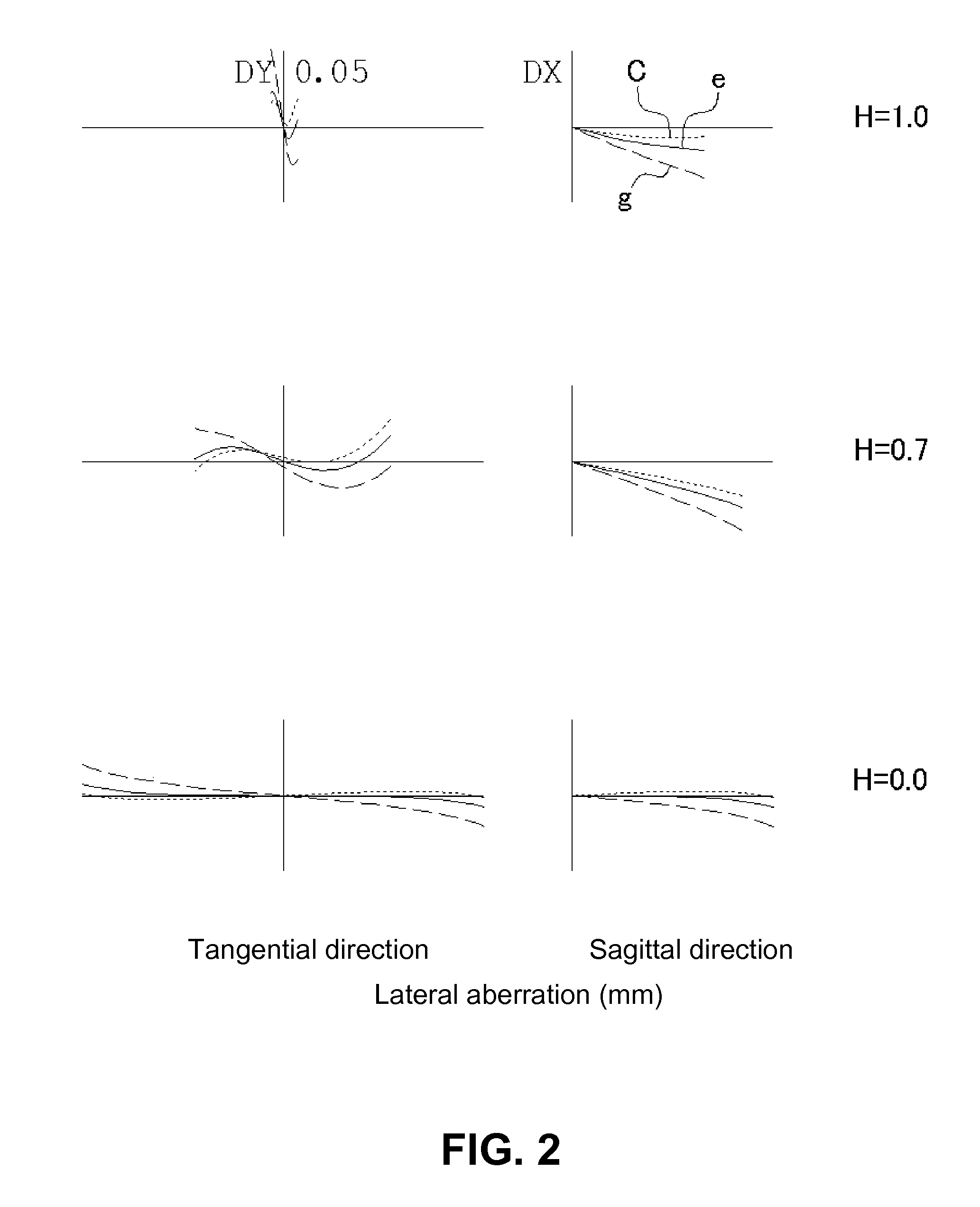
However, since an axial chromatic aberration is insufficiently corrected (a focal position at a short wavelength moves to the object side relative to a focal position at a reference wavelength), it is difficult to obtain satisfactory image-forming performance.
Furthermore, since incident pupil moves to the object side, a back focal length is long, so that it is difficult to downsize the imaging lens.

Method used


Image

  • Imaging lens
  • Imaging lens
  • Imaging lens

Examples


Embodiment Construction

[0057]Hereunder, referring to the accompanying drawings, an embodiment of the present invention will be fully described.

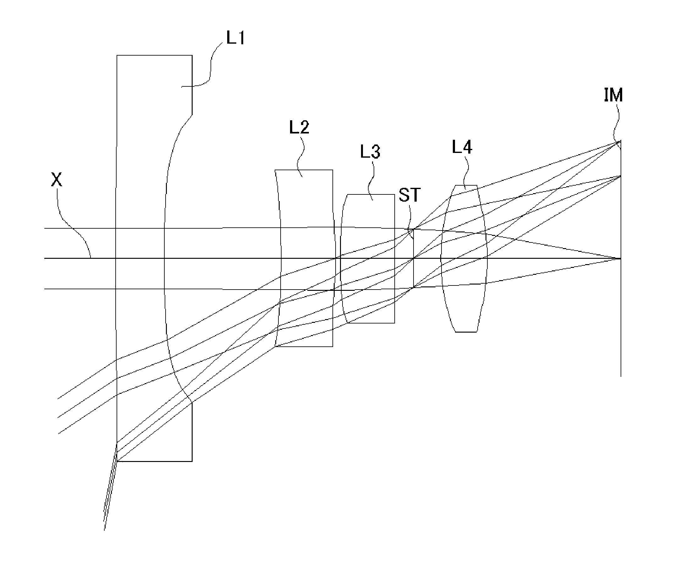
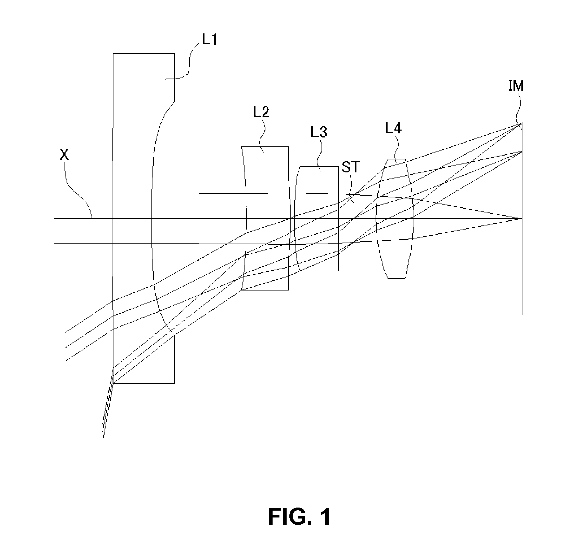
[0058]FIGS. 1, 4, 7, 10, 13, and 16 are schematic sectional views of imaging lenses in Numerical Data Examples 1 to 6 according to the embodiment, respectively. Since a basic lens configuration is the same among those Numerical Data Examples, the lens configuration of the embodiment will be described with reference to the illustrative sectional view of Numerical Data Example 1.

[0059]As shown in FIG. 1, the imaging lens of the embodiment includes a first lens L1 having negative refractive power; a second lens L2 having positive refractive power; a third lens L3 having positive refractive power; an aperture stop ST; and a fourth lens L4 having positive refractive power, arranged in the order from an object side to an image plane side. Here, an infrared cutoff filter, a cover glass, or the like may be provided between the fourth lens L4 and an image plane IM.

[0060]The...


PUM

PropertyMeasurementUnit
temperatureaaaaaaaaaa
angle of viewaaaaaaaaaa
angles of viewaaaaaaaaaa

Abstract

An imaging lens includes a first lens having negative refractive power; a second lens having positive refractive power; a third lens having positive refractive power; a stop; and a fourth lens having positive refractive power arranged in the order from an object side to an image plane side. The first lens has an image plane-side surface having a positive curvature radius. The second lens has an image plane-side surface having negative curvature radius. The third lens has an image plane-side surface having a negative curvature radius. The fourth lens has an object-side surface having a positive curvature radius and an image plane-side surface having a negative curvature radius. The first lens has a specific focal length and a specific Abbe's number to satisfy specific conditional expressions.

Description

BACKGROUND OF THE INVENTION AND RELATED ART STATEMENT[0001]The present invention relates to an imaging lens for forming an image of an object on an imaging element such as a CCD sensor and a CMOS sensor. In particular, the present invention relates to an imaging lens suitable for mounting in a relatively small camera such as a cellular phone, a digital still camera, a portable information terminal, a security camera, a vehicle onboard camera, a network camera, a video conferencing camera, a fiberscope, and an encapsulated endoscope.[0002]In these years, there have been available some vehicles equipped with a plurality of cameras for a purpose of enhancing convenience and security. For example, in case of a vehicle equipped with a backup camera to take an image behind the vehicle, since a driver can see the rear view of the vehicle on a monitor upon backing up the vehicle, the driver can safely move the vehicle backward without hitting an object even if any, although such an object i...

Claims


Application Information

Patent Timeline
Patent Type & Authority Patents(United States)
IPC IPC(8): G02B9/34G02B3/02G02B13/18G02B13/00
CPCG02B13/004G02B1/11G02B9/34G02B27/0025
Inventor KUBOTA, YOJIKUBOTA, KENICHIHIRANO, HITOSHIYONEZAWA, TOMOHIRO
Owner TOKYO VISIONARY OPTICS CO LTD
Learn More