
Medical device packaging with charging interface

a medical device and charging interface technology, applied in the direction of container/bottle construction, rigid containers, and battery arrangement for several simultaneous batteries, etc., can solve the problems of patient infection or other contamination, cumbersome or difficult to maneuver the user's tethering to a wall outlet, and the battery pack is often non-steril

Active Publication Date: 2015-04-07
CILAG GMBH INT
View PDF331 Cites 577 Cited by
  • Summary
  • Abstract
  • Description
  • Claims
  • Application Information

AI Technical Summary

Benefits of technology

The patent text describes a system and method for using energy-based surgical instruments that do not require a power source to function properly. The system includes a charging system for sterilized medical devices that ensures the devices are always ready for use. The use of non-sterile battery packs with the medical devices poses a risk of infection or contamination for patients. The technical effects of the patent text include improved safety and reliability for using energy-based surgical instruments and the ability to maintain sterilization of the instruments.

Problems solved by technology

However, tethering a medical device to a wall outlet may be cumbersome or difficult to maneuver for the user.
Furthermore, in many situations, such medical devices must remain sterile, otherwise a patient may be susceptible to infection or other contamination from being exposed to a non-sterile device.
Battery packs could be used with such medical devices; however, battery packs are often non-sterile.
Thus, using a battery could pose increased risks to a patient.
In the event that a non-sterile battery is used, the non-sterile battery may ultimately become exposed to the medical device, which may compromise the sterility of the medical device for use with a patient.
In short, using a non-sterile power source with a sterile medical device may pose risks.

Method used


Image

  • Medical device packaging with charging interface
  • Medical device packaging with charging interface
  • Medical device packaging with charging interface

Examples


Embodiment Construction

[0034]The following description of certain examples of the invention should not be used to limit the scope of the present invention. Other examples, features, aspects, embodiments, and advantages of the invention will become apparent to those skilled in the art from the following description, which is by way of illustration, one of the best modes contemplated for carrying out the invention. As will be realized, the invention is capable of other different and obvious aspects, all without departing from the invention. Accordingly, the drawings and descriptions should be regarded as illustrative in nature and not restrictive.

[0035]I. Overview

[0036]In some medical procedures, it will be appreciated that medical device such as those taught in U.S. Pat. Nos. 6,500,176, 7,416,101, 7,738,971, U.S. Pub. No. 2009 / 0209990 (now U.S. Pat. No. 8,657,174), U.S. Pub. No. 2006 / 0079874 (now abandoned), U.S. Pub. No. 2007 / 0191713 (now abandoned), U.S. Pub. No. 2007 / 0282333 (now abandoned), and U.S. Pu...


PUM

PropertyMeasurementUnit
frequencyaaaaaaaaaa
frequencyaaaaaaaaaa
open space distanceaaaaaaaaaa

Abstract

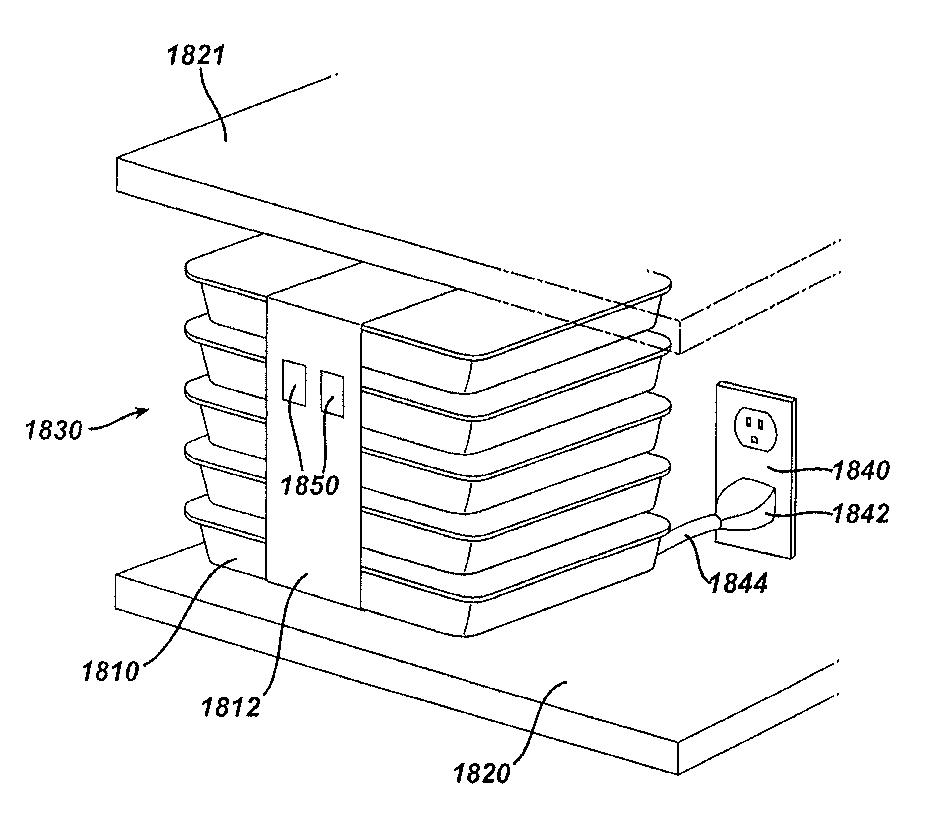
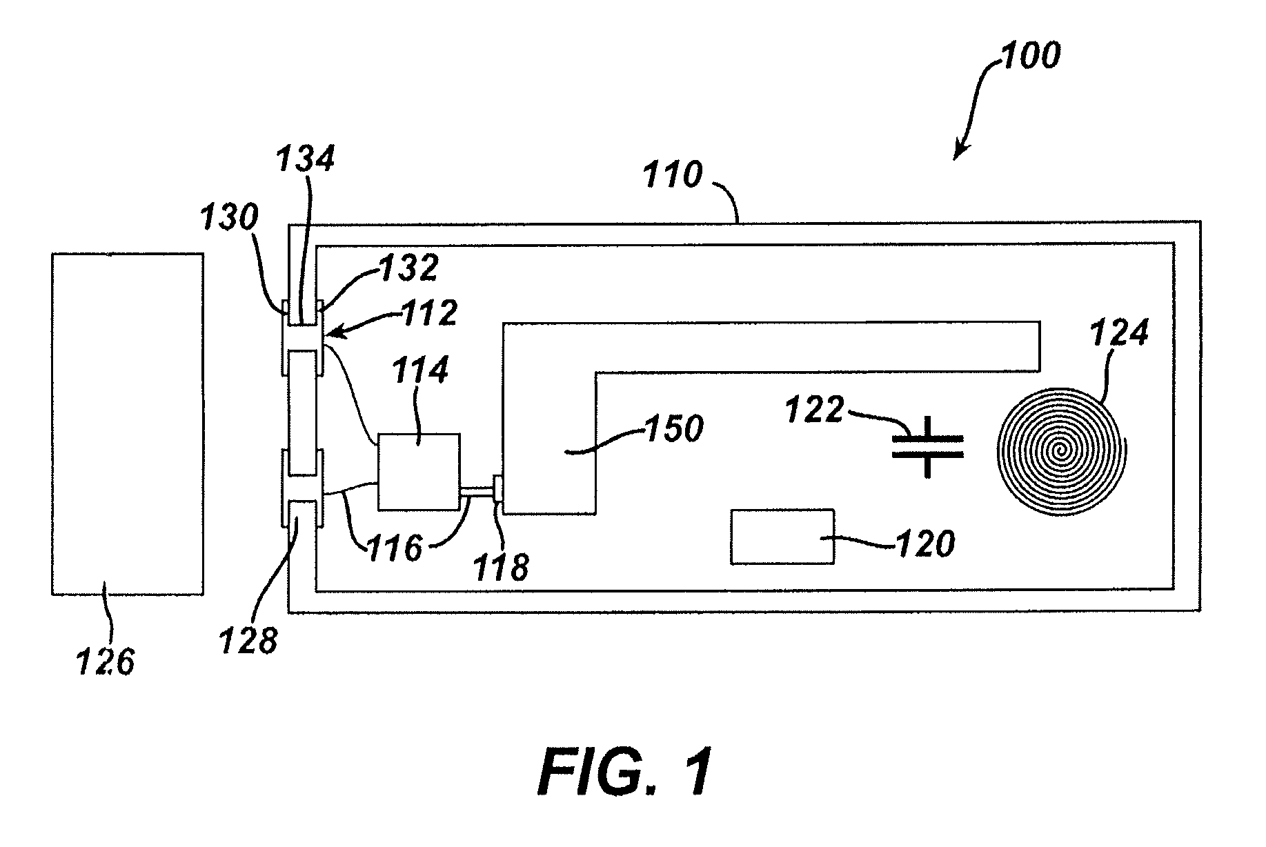
An apparatus for delivering power to an electrically powered medical device includes a package and an electrical coupling feature. The package comprises an interior portion and a wall. The interior portion of the package is able to hold a sterile, electrically powered medical device having a rechargeable battery. The package is able to maintain sterility of the interior portion of the package. The electrical coupling feature may be in communication with the wall of the package and in further communication with the medical device. The electrical coupling feature may be able to deliver power from an external power source to the medical device to charge the battery of the medical device without compromising the sterility of the package or the sterility of the medical device.

Description

PRIORITY[0001]This application claims priority to U.S. Provisional Application Ser. No. 61 / 410,603, filed Nov. 5, 2010, entitled “Energy-Based Surgical Instruments,” the disclosure of which is incorporated by reference herein.[0002]This application also claims priority to U.S. Provisional Application Ser. No. 61 / 487,846, filed May 19, 2011, entitled “Energy-Based Surgical Instruments,” the disclosure of which is incorporated by reference herein.BACKGROUND[0003]Many medical devices require a power source to function properly. In some cases, medical devices may be plugged into a wall outlet to receive power. However, tethering a medical device to a wall outlet may be cumbersome or difficult to maneuver for the user. Furthermore, in many situations, such medical devices must remain sterile, otherwise a patient may be susceptible to infection or other contamination from being exposed to a non-sterile device. Battery packs could be used with such medical devices; however, battery packs a...

Claims


Application Information

Patent Timeline
Patent Type & Authority Patents(United States)
IPC IPC(8): H02J7/00B65D83/10A61B17/32A61B17/00A61B17/064A61B17/285A61B17/29A61B18/00A61B18/04A61B18/12A61B18/14A61B19/00H01M50/227H01M50/247H01M50/271H01M50/531
CPCA61B18/1442A61B17/00234A61B17/320068A61B17/320092A61B18/00A61B18/04A61B18/12A61B18/14A61B18/1445H02J7/0045H01M2/26H01M2/10A61B18/1206A61B17/064A61B17/285A61B18/1233A61B19/38A61B2017/00084A61B2017/00398A61B2017/0046A61B2017/00473A61B2017/00477A61B2017/00482A61B2017/00734A61B2017/291A61B2017/2929A61B2017/293A61B2017/2931A61B2017/2933A61B2017/294A61B2018/00178A61B2018/00791A61B2018/00988A61B2018/1226A61B2018/1412A61B2018/1455A61B2019/4815A61B2019/4868A61B2019/4873A61B90/40A61B2090/0803A61B2090/0813A61B2090/0814H01M50/247H01M50/531H01M10/48H01M50/271H01M50/227G16H20/40G16H40/63Y02E60/10Y10T29/49005Y10T29/49895Y10T29/53913A61B2050/314A61B17/2909A61B2050/0065A61B50/33A61B2017/00411A61B50/30A61B2050/3007A61B50/22H02J7/0044H02J7/02H02J7/00034H02J7/0047H02J50/10H02J50/05H02J7/0013H02J2310/23A61B34/25A61B46/10A61B90/08A61B2017/320094A61B2017/320069A61B2017/320095A61B2017/320071H02J7/0048A61B17/2812A61B2017/0084A61B2018/0019A61B2018/00589A61B2018/00595A61B2018/00601A61B2018/00607A61N7/00H01M10/46H01M2220/30
Inventor STULEN, FOSTER B.ANDERSON, CHRISTOPHER B.SHELTON, IV, FREDERICK E.STOKES, MICHAEL J.DIETZ, TIMOTHY G.MADAN, ASHVANI K.SMITH, BRET W.
Owner CILAG GMBH INT
Learn More