Eureka AIR delivers breakthrough ideas for toughest innovation challenges, trusted by R&D personnel around the world.

Air/fuel ratio control device for internal-combustion engine

a technology of air/fuel ratio and control device, which is applied in the direction of electric control, machines/engines, mechanical apparatus, etc., can solve the problems of thermal degradation in the three-way catalyst, thermal degradation in the three-way catalyst, and so as to achieve further efficient suppression of suppress thermal degradation in the catalyst

Inactive Publication Date: 2015-04-07
TOYOTA JIDOSHA KK
View PDF12 Cites 3 Cited by
  • Summary
  • Abstract
  • Description
  • Claims
  • Application Information

AI Technical Summary

Benefits of technology

[0011]Therefore, it is an object of the invention to suppress thermal degradation in the catalyst in the internal-combustion engine which includes the catalyst having an oxidizing ability and provided in the exhaust passage, wherein the entire air / fuel ratio of the air / fuel mixture is controlled to be the target air / fuel ratio in a manner such that the air / fuel mixture with the air / fuel ratio leaner than the target air / fuel ratio and the air / fuel ratio leaner than the theoretical air / fuel ratio and the air / fuel mixture with the air / fuel ratio richer than the target air / fuel ratio and the air / fuel ratio richer than the theoretical air / fuel ratio are formed in the combustion chamber.
[0017]According to the third aspect, as the amplitude of the air / fuel ratio of the air / fuel mixture when the air / fuel ratio of the air / fuel mixture alternately becomes leaner than the target air / fuel ratio or richer than the target air / fuel ratio with respect to the target air / fuel ratio, when the amplitude of the air / fuel ratio of the air / fuel mixture set according to the air intake amount is larger than the amplitude of the air / fuel ratio of the air / fuel mixture set according to the catalyst temperature, the amplitude of the air / fuel ratio of the air / fuel mixture set according to the catalyst temperature is adopted. In other words, when the amplitude of the air / fuel ratio of the air / fuel mixture set according to the air intake amount is larger than the amplitude of the air / fuel ratio of the air / fuel mixture set according to the catalyst temperature, the amplitude of the air / fuel ratio of the air / fuel mixture set according to the air intake amount is guarded by the amplitude of the air / fuel ratio of the air / fuel mixture set according to the catalyst temperature. Accordingly, thermal degradation in the catalyst is suppressed. That is, the catalyst of the invention has an oxidizing ability. For this reason, when the amounts of oxygen and unburned fuel of the exhaust gas which flows into the catalyst are unchanged, the combustion amount of the unburned fuel in the catalyst becomes larger as the temperature of the catalyst becomes higher, so that the heat generation amount generated by the combustion of the unburned fuel in the catalyst is large. In other words, if the amounts of oxygen and unburned fuel in the exhaust gas which flows into the catalyst are large when the temperature of the catalyst is high, the heat generation amount generated by the combustion of the unburned fuel in the catalyst becomes larger, and hence there is a possibility that thermal degradation in the catalyst may occur. On the contrary, according to the invention, when the amplitude of the air / fuel ratio of the air / fuel mixture set according to the air intake amount is larger than the amplitude of the air / fuel ratio of the air / fuel mixture set according to the catalyst temperature, that is, the amplitude of the air / fuel ratio of the air / fuel mixture set according to the catalyst temperature concerned with thermal degradation in the catalyst, the amplitude of the air / fuel ratio of the air / fuel mixture is guarded by the amplitude of the air / fuel ratio of the air / fuel mixture set according to the catalyst temperature, and the amounts of oxygen and unburned fuel in the exhaust gas which flows into the catalyst decreases. As a result, thermal degradation in the catalyst is suppressed.
[0020]Further, according to the fourth aspect, it is determined whether the amplitude set according to the air intake amount is adopted as the amplitude for the actual air / fuel ratio control or the amplitude set according to the catalyst temperature is adopted as the amplitude for the actual air / fuel ratio control when the catalyst temperature is higher than a predetermined temperature, that is, there is an increasing possibility that thermal degradation in the catalyst may occur. For this reason, thermal degradation in the catalyst is further efficiently suppressed.
[0025]Further, according to the sixth aspect, it is determined whether the amplitude set according to the air intake amount is adopted as the amplitude for the actual air / fuel ratio control or the amplitude set according to the catalyst temperature is adopted as the amplitude for the actual air / fuel ratio control when the catalyst temperature is higher than a predetermined temperature, that is, there is an increasing possibility that thermal degradation in the catalyst may occur. For this reason, thermal degradation in the catalyst is further efficiently suppressed.

Problems solved by technology

Here, when an increase in the temperature of the three-way catalyst is very large, there is a possibility that thermal degradation in the three-way catalyst may occur.
For this reason, there is a possibility that thermal degradation in the three-way catalyst may occur as in the above-described internal-combustion engine.
However, also in the internal-combustion engine in which the catalyst having the oxidizing ability is provided in the exhaust passage, when the exhaust gas with the air / fuel ratio leaner than the theoretical air / fuel ratio and the exhaust gas with the air / fuel ratio richer than the theoretical air / fuel ratio alternately flow into the catalyst for amother purpose, there is a possibility that thermal degradation in the catalyst may occur as in the above-described internal-combustion engine.

Method used


Image

  • Air/fuel ratio control device for internal-combustion engine
  • Air/fuel ratio control device for internal-combustion engine
  • Air/fuel ratio control device for internal-combustion engine

Examples


first embodiment

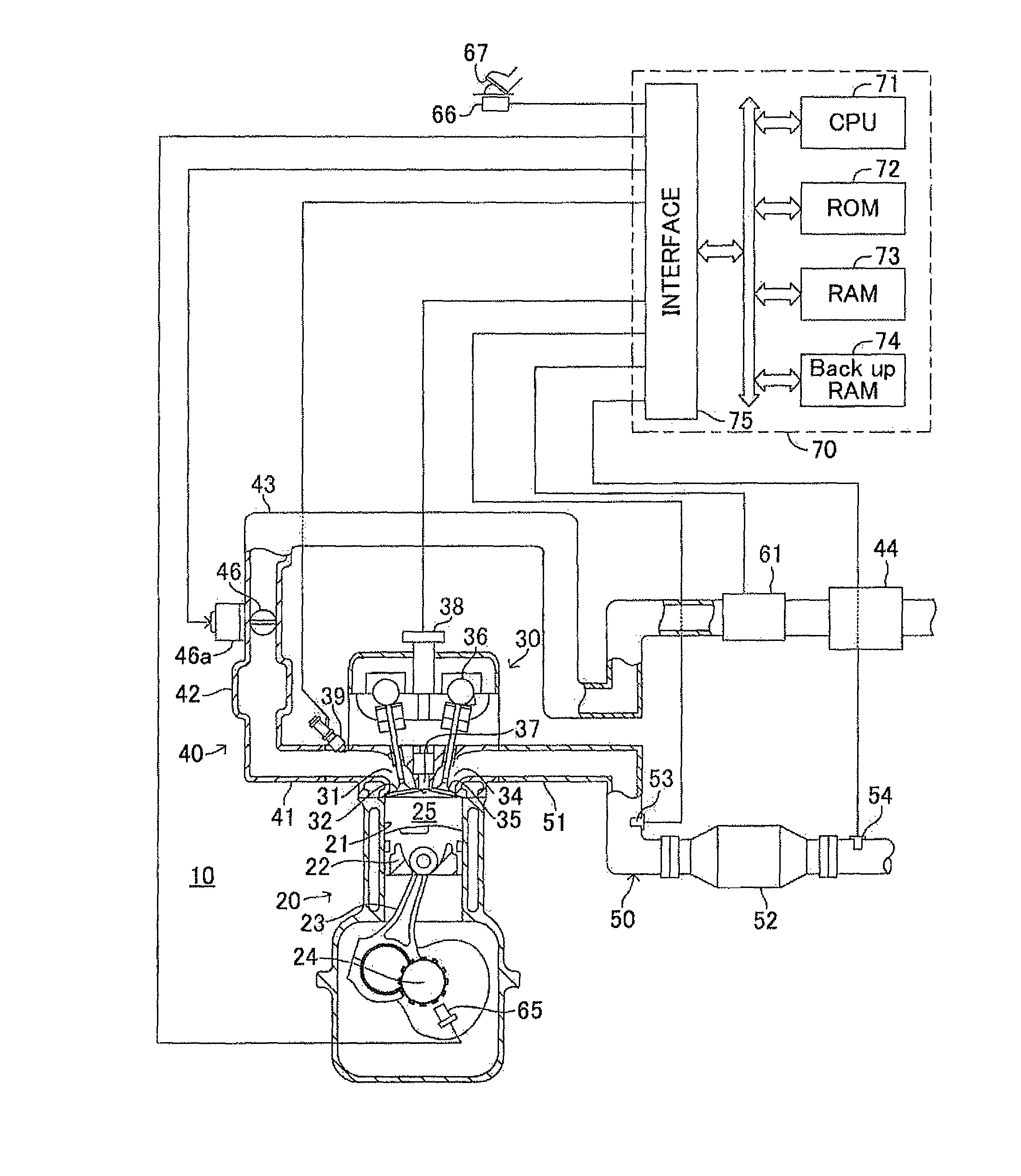
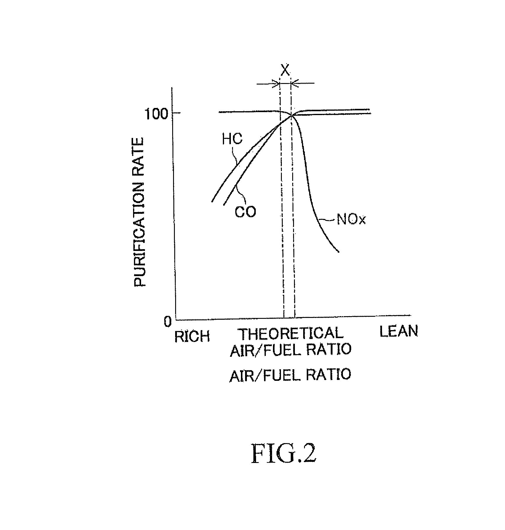
[0053]Incidentally, as described above, the three-way catalyst 52 may simultaneously purify NOx, CO, and HC at a high purification rate when the air / fuel ratio of the exhaust gas which flows thereinto is near the theoretical air / fuel ratio. Accordingly, from the viewpoint that the high purification rate in the three-way catalyst is ensured, it is desirable that the air / fuel ratio of the air / fuel mixture formed in the combustion chamber 25 be controlled to be the theoretical air / fuel ratio. Therefore, in the embodiment (hereinafter, referred to as a ‘first embodiment’), when the running state of the internal-combustion engine (hereinafter, this will be referred to as an ‘engine running state’) is in a normal state, stoichiometric control is executed as below so that the air / fuel ratio of the air / fuel mixture is controlled to be the theoretical air / fuel ratio.

[0054]That is, in the normal stoichiometric control of the first embodiment, the amount of air which is suctioned to the combus...

second embodiment

[0102]That is, as described above, the three-way catalyst 52 has the oxygen absorbing and discharging ability in which the three-way catalyst absorbs oxygen in the exhaust gas when the air / fuel ratio of the exhaust gas flowing thereinto is leaner than the theoretical air / fuel ratio and discharges oxygen absorbed thereto when the air / fuel ratio of the exhaust gas flowing thereinto is richer than the theoretical air / fuel ratio. Accordingly, when the air / fuel ratio of the exhaust gas which flows into the three-way catalyst is leaner than the theoretical air / fuel ratio, the three-way catalyst absorbs oxygen in the exhaust gas. However, there is a limitation in the amount of oxygen which may be absorbed to the three-way catalyst by the unit of time. For this reason, even when the air / fuel ratio of the exhaust gas flowing into the three-way catalyst is leaner than the theoretical air / fuel ratio, there is a possibility that the three-way catalyst may not absorb the entire oxygen in the exh...

third embodiment

[0154]Next, another example of a flowchart which executes the control of the air / fuel ratio of the air / fuel mixture will be described. In this example, the flowcharts of FIGS. 19 to 22 and 5 are used. Furthermore, since the flowchart of FIG. 5 has been already described, the description thereof will not be repeated.

[0155]When the routine of FIG. 19 is started, first, in step 600, it is determined whether the execution of the stoichiometric control is demanded. Here, when it is determined that the execution of the stoichiometric control is demanded, the routine proceeds to step 601 and the steps thereafter. On the other hand, when it is determined that the execution of the stoichiometric control is not demanded, the routine proceeds to step 113 and the steps thereafter of FIG. 5 and the rich control is executed or the fuel cut control is executed.

[0156]In step 600 of FIG. 19, when it is determined that the execution of the stoichiometric control is demanded and the routine proceeds ...


PUM


Abstract

An internal-combustion engine of the invention includes a catalyst which has an oxidizing ability and is provided in an exhaust passage, wherein an air / fuel ratio of an air / fuel mixture is controlled so that the air / fuel ratio leaner than a theoretical air / fuel ratio and the air / fuel ratio richer than the theoretical air / fuel ratio are alternated with a predetermined amplitude with respect to a target air / fuel ratio. On the assumption that the temperature of the catalyst is referred to as a catalyst temperature, an amplitude set according to the catalyst temperature is adopted as the predetermined amplitude, and the amplitude set when the catalyst temperature is higher than a predetermined temperature is smaller than the amplitude set when the catalyst temperature is lower than the predetermined temperature.

Description

BACKGROUND OF THE INVENTION[0001]1. Technical Field[0002]The present invention relates to an air / fuel ratio control device for an internal-combustion engine.[0003]2. Background Art[0004]Japanese Patent Application Laid-Open No. H09-126015 discloses an air / fuel ratio control device for an internal-combustion engine. In the air / fuel ratio control device, the amount of fuel which is injected from a fuel injection valve is increased when the state of the internal-combustion engine is in a high load region, which decreases the temperature of an exhaust gas discharged from a combustion chamber and suppresses thermal degradation in the catalyst disposed in an exhaust passage. In this way, in the internal-combustion engine in which the catalyst is disposed in the exhaust passage, there has been a demand for suppressing thermal degradation in the catalyst.[0005]Incidentally, in the field of the internal-combustion engine, there is a known three-way catalyst capable of simultaneously purifyin...

Claims


Application Information

Patent Timeline
Patent Type & Authority Patents(United States)
IPC IPC(8): F01N3/00F02D41/02F02D41/14
CPCF02D41/1475F02D41/0235F02D2041/0265F02D2200/0802Y02T10/22F02D41/0295F01N3/101Y02T10/12
Inventor YOSHIOKA, MAMORU
Owner TOYOTA JIDOSHA KK
Why Eureka
Eureka Blog
Learn More