
Guides with pressure points

a technology of pressure points and guides, applied in the field of guides with pressure points, can solve problems such as deviations from surgical planning, operator uncertainty, and incorrect placement of patient-specific devices

Active Publication Date: 2015-03-24
MATERIALISE NV
View PDF14 Cites 20 Cited by
  • Summary
  • Abstract
  • Description
  • Claims
  • Application Information

AI Technical Summary

Benefits of technology

The solution ensures accurate and stable positioning of patient-specific devices, enhancing the precision and reliability of orthopedic procedures by allowing operators to confidently maintain the devices in the correct pre-defined location.

Problems solved by technology

The actual placement and maintenance of the patient-specific device in the correct position is not always straightforward for the operator, leading to uncertainty for the operator and possible incorrect placement of the patient-specific device and thus deviations from the surgical planning.

Method used


Image

  • Guides with pressure points
  • Guides with pressure points
  • Guides with pressure points

Examples


example 1

[0086]The present example provides a detailed description of a specific embodiment wherein an envisioned patient-specific device is improved by providing thereon a push feature for accurately positioning said device.

[0087]In order to identify the optimal position and orientation of the push feature, the axis of least-constrained direction for rotation and translation must be determined. This is illustrated in FIGS. 1A and 1B.

[0088]The present example starts from an existing patient-specific guide. The contact surface (2) of said guide on the anatomical part (1) is identified (see FIG. 2A), and data related to the contact surface may be imported into a computing environment, such as Matlab. The faces of the contact surface (2) are represented by their midpoints with coordinates ri and unit outward normal vector ni, A wrench vector wi, is created for each of the N different contact points using formula (1).

[0089]wi=[nini×ri](1)

[0090]As the preprocessing phases may result in an irregul...

example 2

[0104]The present example, illustrated by FIGS. 3 and 4, provides various alternative push features that can be provided onto a patient specific device. The push features may for instance be a finger-pit (FIG. 3A), one or more buttons (FIG. 3B), a handle (FIG. 4A), a grip (FIGS. 4B and 4C) or a handle provided with one or more finger pits or buttons (FIG. 3C).

example 3

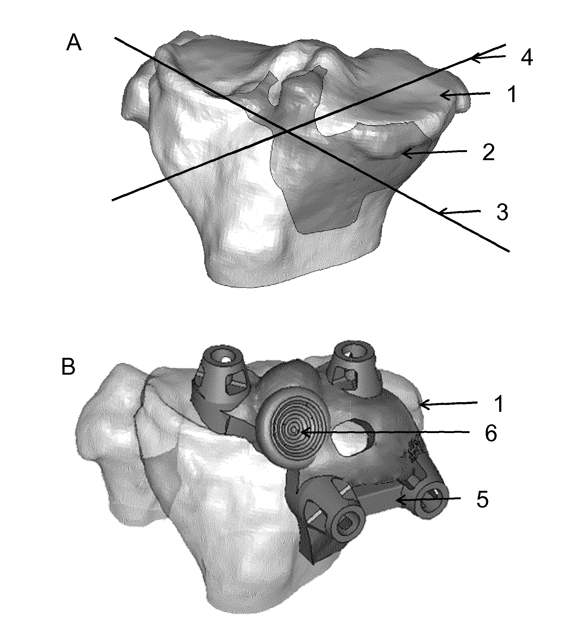
[0105]FIGS. 5 A and B illustrate a patient-specific device according to particular embodiments. The patient-specific device is a surgical guide for guiding a shoulder surgery, and comprises a support structure (7) and a guiding feature (8), more particularly a drill guide. The surgical guide is intended for positioning onto an anatomical part (1), more particularly a patient's glenoid. Therefore comprises several patient-specific contact surfaces (2) which are at least partially complementary to surfaces on or around a patient's glenoid. FIGS. 6 A and B illustrates a shoulder joint, with the patient-specific surgical device (5) positioned on the glenoid (1) via the contact surfaces.

[0106]The guide comprises a dedicated push feature (6), more particularly a handle. The orientation and position of the handle facilitates applying a force to the device perpendicular to the axis of least-constrained rotational direction of the guide on the glenoid, parallel to the axis of least-constrain...


PUM

PropertyMeasurementUnit
forceaaaaaaaaaa
pressureaaaaaaaaaa
magnetic resonance imageaaaaaaaaaa

Abstract

The application provides methods for providing a surgical guide for placement on an anatomical part wherein the guide is provided with one or more dedicated push features that can be used as pressure points for applying force onto the surgical guide. The application further provides guides comprising one or more push features which can be used as a pressure point for applying force onto said guide.

Description

CROSS-REFERENCE TO RELATED APPLICATIONS[0001]This application is a continuation under 35 U.S.C. §120 of International Application No. PCT / EP2012 / 071258, filed Oct. 26, 2012 (and published by the International Bureau as International Publication No. WO 2013 / 060842 on May 2, 2013), which claims the benefit of U.S. Provisional Patent Application No. 61 / 552,510, filed Oct. 28, 2011, and which also claims priority to European Application No. 11187145.5, filed Oct. 28, 2011. Each of the above referenced patent applications is hereby incorporated by reference in its entirety.BACKGROUND OF THE INVENTION[0002]The present application relates to methods for providing surgical guides for placement on an anatomical part, wherein the guide is provided with one or more dedicated push features that can be used to apply force onto the surgical guide.[0003]Conventional orthopedic prostheses and implants, such as knee and hip implant systems, have been in use for many years with considerable success. ...

Claims


Application Information

Patent Timeline
Patent Type & Authority Patents(United States)
IPC IPC(8): B23Q17/00A61F2/46A61B17/00A61B17/15A61B17/17A61B17/56A61B17/68A61B17/90A61B19/00A61F2/28A61F2/30
CPCA61B19/50A61B17/1739A61F2/30A61B17/17A61B17/68A61F2/28A61F2/30942A61B2017/0042A61B2017/00526A61B2017/1778A61B2017/568A61B2017/90A61B17/155A61B17/157A61B2019/508A61B34/10A61B2034/108A61B17/1778B29C64/386Y10T29/49764A61B17/90G06F30/00B33Y50/02G06F17/16
Inventor BROECK, JOYCE VAN DENDAEMEN, NELENIKONENKO, KATERINASTEPANENKO, MARYNA
Owner MATERIALISE NV
Learn More