
Image processing device, image processing method and storage medium to suppress shading of images in which pixel addition processing is performed

a technology of image processing and image processing method, which is applied in the field of image processing device, image processing method and storage medium to suppress image shading, can solve the problems of peripheral light loss, tone jump, and light amount reduction, and achieve the effect of suppressing image shading

Inactive Publication Date: 2015-03-03
CASIO COMPUTER CO LTD
View PDF14 Cites 1 Cited by
  • Summary
  • Abstract
  • Description
  • Claims
  • Application Information

AI Technical Summary

Benefits of technology

Effectively suppresses shading in images by accurately correcting luminance and color differences, maintaining color balance in HDR images and preventing excessive correction or irregularities, thus enhancing image quality by avoiding luminance saturation and tone jumps.

Problems solved by technology

Heretofore, when images through lenses have been captured in digital cameras, there have been occurrences of peripheral light loss (shading), in which light amounts decrease with distance from the center point of a lens toward the periphery.
However, in the case of a high dynamic range (HDR) image, which is generated by processing that performs pixel addition of successively shot images with different exposure times, excessive correction may be applied to periphery portions of the image and luminance values may be saturated (“whiteouts”), and in the case of a basically dark image, there may be irregularities in a shading correction gain characteristic from the central portion of the image to peripheral portions, and tone jumps may occur.

Method used


Image

  • Image processing device, image processing method and storage medium to suppress shading of images in which pixel addition processing is performed
  • Image processing device, image processing method and storage medium to suppress shading of images in which pixel addition processing is performed
  • Image processing device, image processing method and storage medium to suppress shading of images in which pixel addition processing is performed

Examples


first embodiment

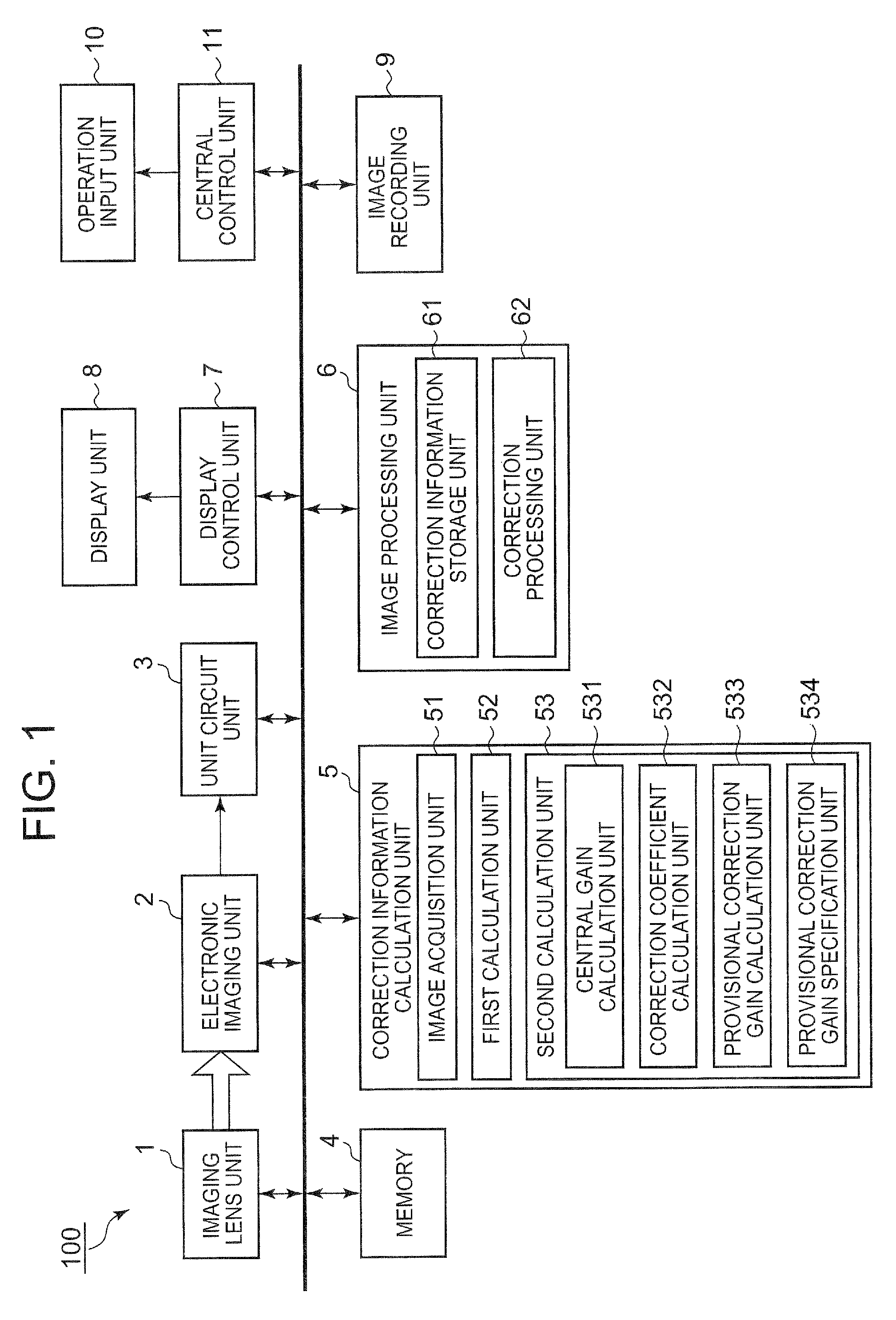
[0051]FIG. 1 is a block diagram showing schematic structure of an imaging device 100 according to a first embodiment in which the present invention is employed.

[0052]As shown in FIG. 1, the imaging device 100 is provided with an imaging lens unit 1, an electronic imaging unit 2, a unit circuit unit 3, a memory 4, a correction information calculation unit 5, an image processing unit 6, a display control unit 7, a display unit 8, an image recording unit 9, an operation input unit 10, and a central control unit 11.

[0053]Although not illustrated, the imaging lens unit 1 includes, for example, a variety of optical lenses, an aperture and the like, through which it focuses an optical image of an object.

[0054]The imaging lens unit 1 is also equipped with an optical zoom mechanism, which is constituted with plural optical lenses.

[0055]A focusing distance of the imaging lens unit 1 is altered by, of the plural optical lenses, the position of a zoom adjustment lens (not shown in the drawings)...


PUM


Abstract

An imaging device 100 is equipped with an image acquisition unit 51, a first calculation unit 52 and a correction information calculation unit 53. The image acquisition unit 51 acquires image data including a luminance component and color components, via an optical system. The first calculation unit 52 detects shading of the luminance component included in the image data, and detects shading of the color difference components. The correction information calculation unit 53 calculates luminance shading correction coefficients and color difference shading correction coefficients. The correction information calculation unit 53 then converts the calculated color difference shading correction coefficients so as to have predetermined ratios with respect to the calculated luminance shading correction coefficients. A correction processing unit 62 corrects plural sets of image data on the basis of the converted color difference shading correction coefficients, and then performs pixel addition of the images.

Description

[0001]This application is based on and claims the benefit of priority from Japanese Patent Application No. 2011-185039, filed on 26 Aug. 2011, the content of which is incorporated herein by reference.BACKGROUND OF THE INVENTION[0002]1. Field of the Invention[0003]The present invention relates to an image processing device, an image processing method and a storage medium.[0004]2. Related Art[0005]Heretofore, when images through lenses have been captured in digital cameras, there have been occurrences of peripheral light loss (shading), in which light amounts decrease with distance from the center point of a lens toward the periphery.[0006]Shading has become significant in recent years, for reasons such as increases in magnification ratios, reductions in size of the lenses themselves and so forth.[0007]In order to reduce shading, Japanese Unexamined Patent Publication No. 2007-134903 discloses a technology that performs shading correction, multiplying output signals from an imaging co...

Claims


Application Information

Patent Timeline
Patent Type & Authority Patents(United States)
IPC IPC(8): H04N9/64H04N5/217G06K9/40H04N1/40H04N5/232H04N9/68H04N23/76
CPCH04N5/3572H04N9/045H04N25/61H04N23/10H04N25/134
Inventor MURAYAMA, YOICHI
Owner CASIO COMPUTER CO LTD
Learn More