
Measurement device of position of center of gravity of vehicle to be measured on truck scale and truck scale

a technology of measurement device and center of gravity, which is applied in the direction of instruments, transportation items, analogue processes for specific applications, etc., can solve the problems of easy rollover, increased risk of rollover, and difficulty in visual inspection of the location of the vehicle, so as to increase the risk of rollover, the structure of the apparatus for determining the center of gravity of the vehicle is extremely simple, and the vehicle center of gravity is high

Active Publication Date: 2015-03-03
KAMACHO SCALE
View PDF10 Cites 7 Cited by
  • Summary
  • Abstract
  • Description
  • Claims
  • Application Information

AI Technical Summary

Benefits of technology

[0094]The invention of the apparatus for determining the center of gravity of the vehicle of the truck scale according to claim 1 of the present application produces an advantage in that the apparatus can measure the weight of the vehicle to be measured by use of the truck scale and, at the same time, calculate the height of the center of gravity of the vehicle to be measured, which has been impossible with an existing truck scale. Generally, the higher the center of gravity of the vehicle, the higher the risk of rollover in driving situations. Thus, by knowing the height of the center of gravity of the vehicle in the aforementioned manner, it is possible to predict the risk of rollover of the vehicle in a road driving situation and to know in advance if the vehicle in the present situation has a secure safety level with respect to a rollover incidence.
[0095]Also, while the invention of claim 1 of the present Application uses the measuring table provided with the front wheel platform located at a position in the frontal part of the flat surface and raised to a specific height and the wheel position detector for detecting the positions of the front and rear wheels for calculating the height of the center of gravity of the vehicle to be measured, other features of the apparatus can be achieved by incorporating various kinds of means for calculating the height of the center of gravity of the vehicle in a central processing unit of an existing truck scale. Therefore, the invention also provides such an advantage that the structure of the apparatus for determining the center of gravity of the vehicle is extremely simple and thus can be manufactured at low cost.
[0096]Additionally, this apparatus for determining the center of gravity of the vehicle of claim 1 makes it possible to calculate the center of gravity along the front / rear direction of the vehicle to be measured by the longitudinal center-of-gravity position calculation means in a process of calculating the height of the center of gravity of the vehicle to be measured, and thereby recognize an imbalance of loaded cargo along the front / rear direction.Advantages of the Invention of claim 2
[0097]The invention of claim 2 of the present application makes it possible to determine the distance between the front and rear axles by calculation as a result of detection by the vehicle position detector. It is therefore possible to calculate the height of the center of gravity of the vehicle even if the distance between the front axle and rear axle is unknown.Advantages of the Invention of claim 3
[0098]The invention of claim 3 of the present Application makes it possible to store the distance between the front and rear axles of the vehicle to be measured in the vehicle inclination angle storage means on the basis of an actual measurement value, so that the vehicle inclination angle calculation means can calculate the longitudinal inclination angle on the basis of the accurate distance between the front and rear axles. The eventually calculated height of the center of gravity of the vehicle is therefore highly reliable.Advantages of the Invention of claim 4
[0099]According to the invention of claim 4 of the present Application, the front axle load and the rear axle load of the vehicle to be measured are measured by a separately provided axle-load scale, and the front axle load and the rear axle load thus measured in advance can be stored in the front axle load storage means and the rear axle load storage means, respectively, before weighing the vehicle to be measured by the truck scale, so that it becomes unnecessary to calculate the front axle load and the rear axle load by the central processing unit at the time of actual weighing on the truck scale. It is therefore possible to simplify the structure.Advantages of the Invention of claim 5

Problems solved by technology

Meanwhile, if a steering wheel is turned sharply when a truck (especially a truck carrying a high-profile cargo box or container) is running, a great centrifugal force acts on the entirety of the truck, causing the truck to become liable to easily roll over.
Especially when the center of gravity of the vehicle is located at a high position and displaced leftward or rightward, a resultant synergistic effect creates a great centrifugal force (causing a rollover accident to become more likely to occur).
Incidentally, one can hardly tell by visual inspection whereabouts the center of gravity of the entirety of the vehicle is under conditions where individual loads are already in the box or the container on the bed of the truck.
Thus, when the center of gravity of the vehicle is located at a high position or greatly displaced leftward or rightward, there has been a risk of a rollover accident potentially caused by a sharp turn of a steering wheel.

Method used


Image

  • Measurement device of position of center of gravity of vehicle to be measured on truck scale and truck scale
  • Measurement device of position of center of gravity of vehicle to be measured on truck scale and truck scale
  • Measurement device of position of center of gravity of vehicle to be measured on truck scale and truck scale

Examples


fifth embodiments

First to Fifth Embodiments

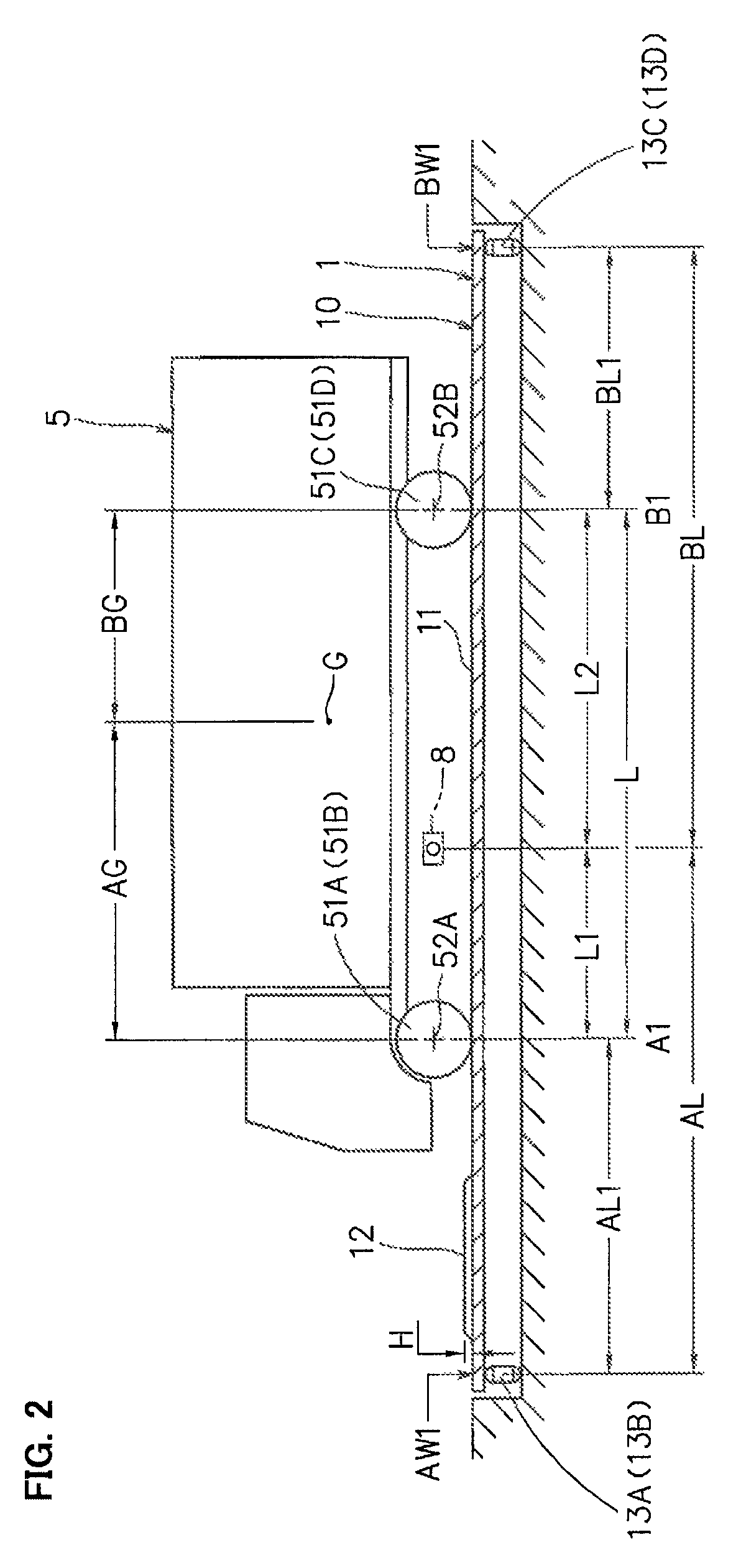
[0134]Referring to FIGS. 1 to 13, an apparatus for determining a vehicle's center of gravity of a truck scale according to each of first to fifth embodiments of the present invention is described. The apparatus for determining the vehicle's center of gravity is configured to be able to determine the center of gravity of a vehicle 5 to be measured by using a truck scale 1 illustrated in FIGS. 1 to 7 and a central processing unit 3 depicted in FIG. 8. Also, FIG. 9 is a detailed block diagram of the apparatus for determining the vehicle's center of gravity according to the first embodiment, FIG. 10 is a detailed block diagram of the apparatus for determining the vehicle's center of gravity according to the second embodiment, FIG. 11 is a detailed block diagram of the apparatus for determining the vehicle's center of gravity according to the third embodiment, FIG. 12 is a detailed block diagram of the apparatus for determining the vehicle's center of gravity ac...

eighth embodiments

Sixth to Eighth Embodiments

[0229]Referring next to FIGS. 14 to 24, sixth to eighth embodiments of the present application are described. FIGS. 14 to 18 depict an apparatus for determining a vehicle's center of gravity according to the sixth embodiment of the present application, FIGS. 19 to 21 depict an apparatus for determining a vehicle's center of gravity according to the seventh embodiment of the present application, and FIGS. 22 to 24 depict an apparatus for determining a vehicle's center of gravity according to the eighth embodiment of the present application. In FIGS. 14 to 24, constituent elements similar to those depicted in FIGS. 1 to 13 are designated by the same symbols.

[0230]The apparatuses for determining the center of gravity of the vehicle depicted in FIGS. 14 to 24 are intended to determine the position where the center of gravity of the vehicle is located along a widthwise direction (left / right direction) thereof. The sixth embodiment depicted in FIGS. 14 to 18 is ...


PUM


Abstract

As a measurement table (10), an object provided with a flat surface (11) having an area on which all wheels of a vehicle can be mounted at the same time and a front wheel mounting table (12) which is disposed in front of the flat surface (11) and is lifted by a step of a predetermined height is used, a wheel position detector (8) which is capable of detecting a front wheel position and a rear wheel position of a vehicle to be measured is provided, a computation processing device (3) is provided with anterior-posterior displacement calculation means, an inter-axle distance calculation means (21), a vehicle inclination calculation means (22), a front wheel axle load calculation means (23A), a rear wheel axle load calculation means (23B), an anterior-posterior gravity center position calculation means (24), a storage means (32), an anterior-posterior gravity center displacement calculation means (25), and a vehicle gravity center height position calculation means (26), and from a gravity center displacement which is calculated from anterior-posterior gravity center position information calculated on the flat surface (11) and anterior-posterior gravity center position information in the state in which front wheels are mounted on the front wheel mounting table (12) and a vehicle inclination which is calculated by the vehicle inclination calculation means (22), the position of the height of the center of gravity of the vehicle to be measured is calculated.

Description

TECHNICAL FIELD[0001]The present invention relates to a truck scale having load cells provided at around four corners of a measuring table for measuring the weight of a vehicle to be measured on the basis of measurement values fed from the individual load cells when all wheels of the vehicle to be measured are placed on the measuring table. More particularly, the invention pertains to an apparatus for determining the center of gravity of a vehicle to be measured on a truck scale which is configured to automatically determine the position of the center of gravity of the vehicle to be measured when the vehicle to be measured is placed on a measuring table.BACKGROUND ART[0002]An example of a truck scale configured to measure the weight of a vehicle to be measured by placing the vehicle on a measuring table is described in Japanese Laid-open Patent Application No. 2006-105845 (Patent Document 1), for instance.[0003]The truck scale of this prior art example (Patent Document 1) includes l...

Claims


Application Information

Patent Timeline
Patent Type & Authority Patents(United States)
IPC IPC(8): G01M1/00G06F17/10G06G7/48B60P1/04G01G19/02G01M1/12G01M17/007
CPCG01M1/122B60P1/045G01G19/021G01G19/02G01M17/007G01M1/12
Inventor KAMADA, TAKEAKITAMURA, TAKASHI
Owner KAMACHO SCALE
Learn More