
MMC cylinder liner and method for producing the same

a technology of cylinder liner and cylinder head, which is applied in the field of mmc cylinder liner, can solve the problems of reducing durability, difficulty in forming a cylinder liner with aluminum alloy, and reducing etc., and achieves the effect of increasing the supply rate of al—si alloy

Inactive Publication Date: 2015-03-03
TOYOTA JIDOSHA KK +1
View PDF11 Cites 0 Cited by
  • Summary
  • Abstract
  • Description
  • Claims
  • Application Information

AI Technical Summary

Benefits of technology

The patent describes a method for producing a cylinder liner made of metal matrix composite (MMC) with inner and outer tubular portions. The inner portion is made of a compact reinforced with an Al-Si alloy, while the outer portion is made of the same alloy. The method involves fitting a compact over a core and providing a mold around the compact to form a cavity in a tubular form. A melted Al-Si alloy is then supplied to the cavity at an increased supply rate to improve the quality of the cylinder liner. The technical effects include improved quality and efficiency of production of MMC cylinder liners.

Problems solved by technology

Meanwhile, it was believed difficult to form a cylinder liner with an aluminum alloy because higher high-temperature dimensional stability, higher abrasion resistance, greater strength, and greater rigidity are required due to the size, function, and operation of the cylinder liner.
However, in that case, mechanical characteristics required for the inner peripheral surface of the cylinder liner that serves as a sliding surface of a piston may not be achieved.
This may cause decrease in durability or add the necessity of further reinforcement with an increased amount of the reinforcing material.

Method used


Image

  • MMC cylinder liner and method for producing the same
  • MMC cylinder liner and method for producing the same
  • MMC cylinder liner and method for producing the same

Examples


first embodiment

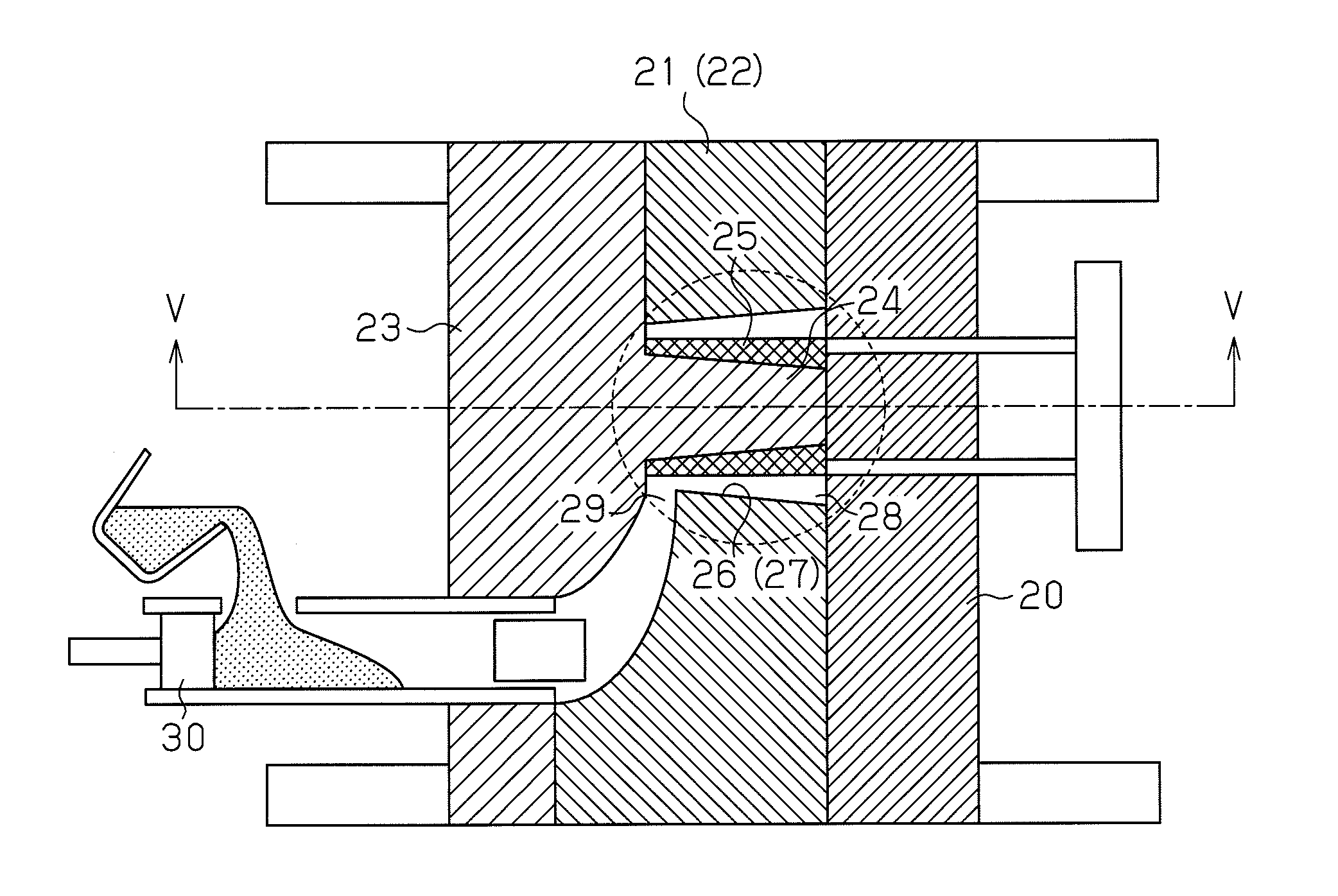
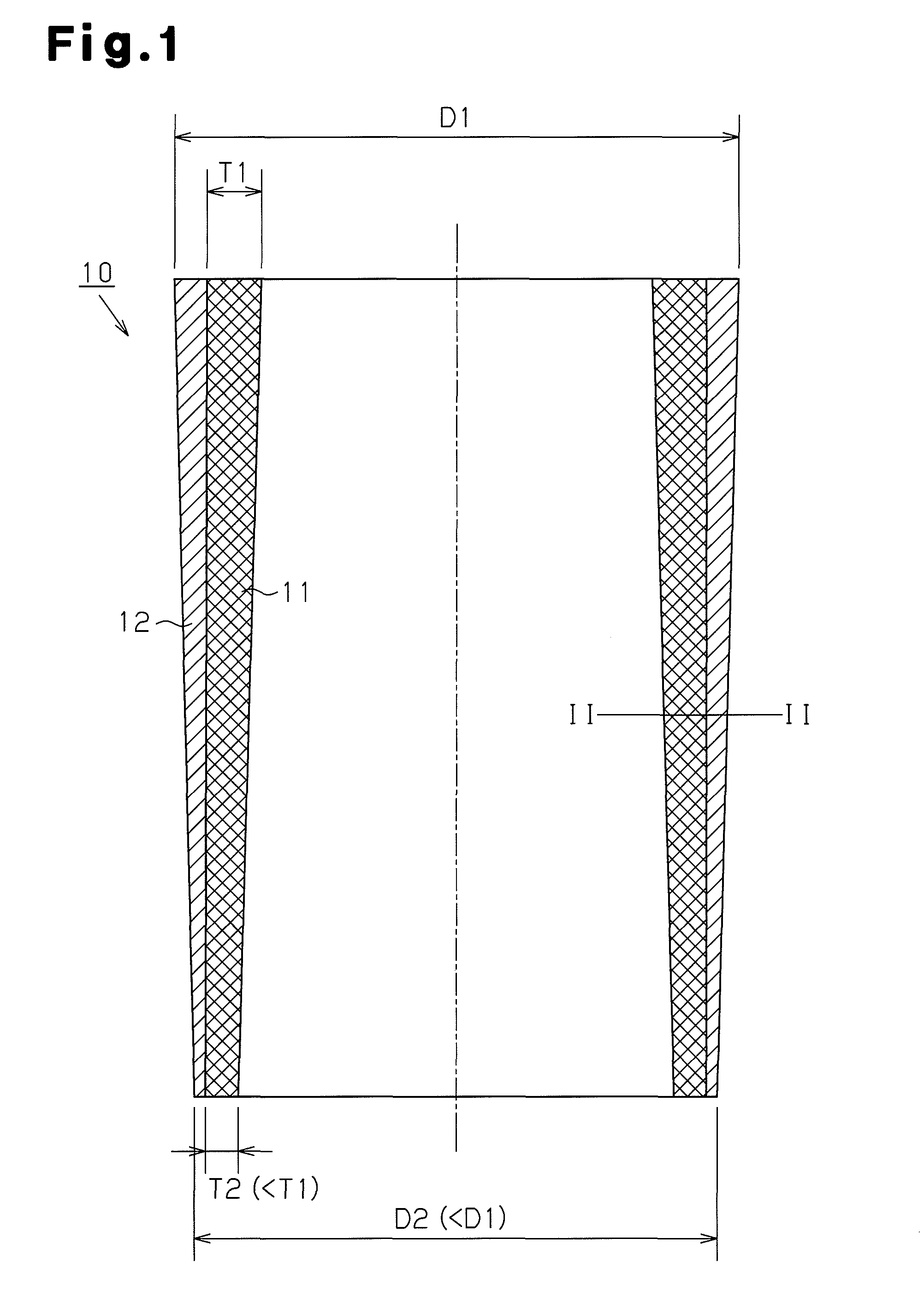
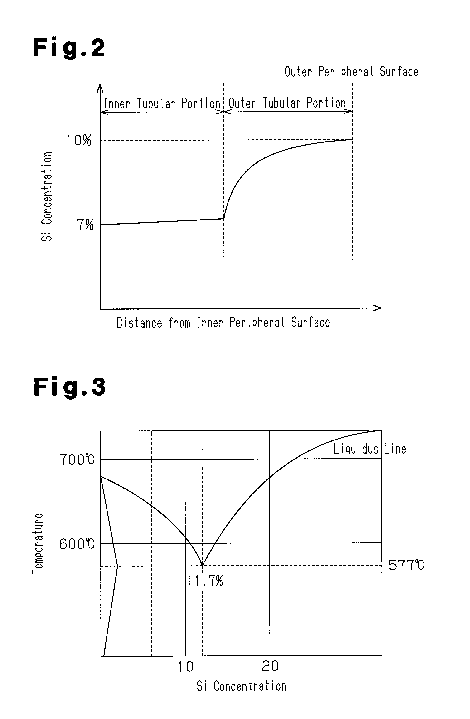
[0037]An MMC cylinder liner according to the first embodiment of the invention and a method for producing the same will be described with reference to FIGS. 1 to 8. First, configuration of the MMC cylinder liner of this embodiment will be explained with reference to FIGS. 1 to 3.

[0038]FIG. 1 illustrates a side cross-sectional view of an MMC cylinder liner 10 according to the first embodiment. The MMC cylinder liner 10 is formed in a generally tubular form having a generally circular cross-section. The MMC cylinder liner 10 includes an inner tubular portion 11 and an outer tubular portion 12. The inner tubular portion 11 includes metal matrix composite (MMC) formed of a reinforcing material impregnated with an Al—Si alloy. The reinforcing material is made of a combination of metal and ceramic fibers or a combination of metal and ceramic particles. The outer tubular portion 12 is formed of the Al—Si alloy.

[0039]As illustrated in FIG. 1, the outer diameter of the outer tubular portion ...

second embodiment

[0061]An MC cylinder liner and a method of making the same according to the second embodiment of the invention will be described with reference to FIG. 9 by focusing different points from the first embodiment.

[0062]The shape of the MMC cylinder liner of the second embodiment is the same as that of the first embodiment in that the MMC cylinder liner of the second embodiment also includes an inner tubular portion 11 formed of the metal matrix composite (MMC) and an outer tubular portion 12 formed of an Al—Si alloy, wherein the metal matrix composites (MMC) includes a compact made of reinforcing material impregnated with the Al—Si alloy. The MMC cylinder liner 10 of the second embodiment is also the same as that of the first embodiment in that the outer diameter of the outer tubular portion 12 is gradually reduced as it goes from one end to the other end in the direction of the longitudinal direction thereof, and the thickness of the inner tubular portion 11 is also gradually reduced f...


PUM

PropertyMeasurementUnit
concentrationaaaaaaaaaa
outer diameteraaaaaaaaaa
thicknessaaaaaaaaaa

Abstract

An MMC cylinder liner comprises an inner tubular portion and an outer tubular portion. The inner tubular portion includes a metal matrix composite formed of a compact impregnated with an Al—Si alloy wherein the compact is made of a reinforcing material. The outer tubular portion is formed of the Al—Si alloy. The Si concentration of the Al—Si alloy impregnated into the compact of the inner tubular portion is different from the Si concentration of the Al—Si alloy of the outer tubular portion.

Description

CROSS REFERENCE TO RELATED APPLICATIONS[0001]This application is a National Stage of International Application No. PCT / JP2010 / 054720 filed on Mar. 12, 2010, which claims priority from Japanese Patent Application No. 2009-085863, filed on Mar. 31, 2009, the contents of all of which are incorporated herein by reference in their entirety.FIELD OF THE INVENTION[0002]This invention relates to an MMC cylinder liner comprising an inner tubular portion and an outer tubular portion, wherein the inner tubular portion includes metal matrix composite formed of a compact impregnated with an Al—Si alloy, the compact being made of a reinforcing material, and wherein the outer tubular portion is formed of the Al—Si alloy.BACKGROUND ART[0003]It is well known that more engine parts are made of an aluminum alloy to satisfy the requirements such as reduction in weight or improvement in heat dissipation. Parts that slide in a reciprocating way at high speed, such as a piston head and a piston ring, exer...

Claims


Application Information

Patent Timeline
Patent Type & Authority Patents(United States)
IPC IPC(8): B23P11/00B22D17/10B22D17/20B22D19/00B22D19/02B22D19/14B22D19/16B22F5/10C22C49/06
CPCB22D19/14B22D17/10B22D17/2069B22D19/0009B22D19/02B22D19/16B22F5/106C22C49/06B22F2207/01Y10T29/49272Y10T29/4998Y10T29/49988
Inventor TAKAMI, TOSHIHIROTSUKIMOTO, MANABUMATSUDAIRA, JUNICHIKUMAGAI, KUNIOSUZUKI, IKUOFUJITA, MAKOTO
Owner TOYOTA JIDOSHA KK
Learn More