
A developing unit and a method for controlling the developing unit

A technology of developing unit and control method, applied in instruments, equipment of electric recording process applying charge pattern, optics, etc., can solve the problems of developer agglomeration, developer waste, developer residue, etc., to avoid agglomeration or Deposition, avoidance of serious waste, the effect of simplified mechanical structure

Active Publication Date: 2022-06-07
NINESTAR CORP
View PDF0 Cites 0 Cited by
  • Summary
  • Abstract
  • Description
  • Claims
  • Application Information

AI Technical Summary

Problems solved by technology

[0004] In this structural design of the agitator, due to the large size of the agitator, the developer storage capacity of the developing unit is reduced, and the user needs to frequently replace the developing unit during use, causing inconvenience to use
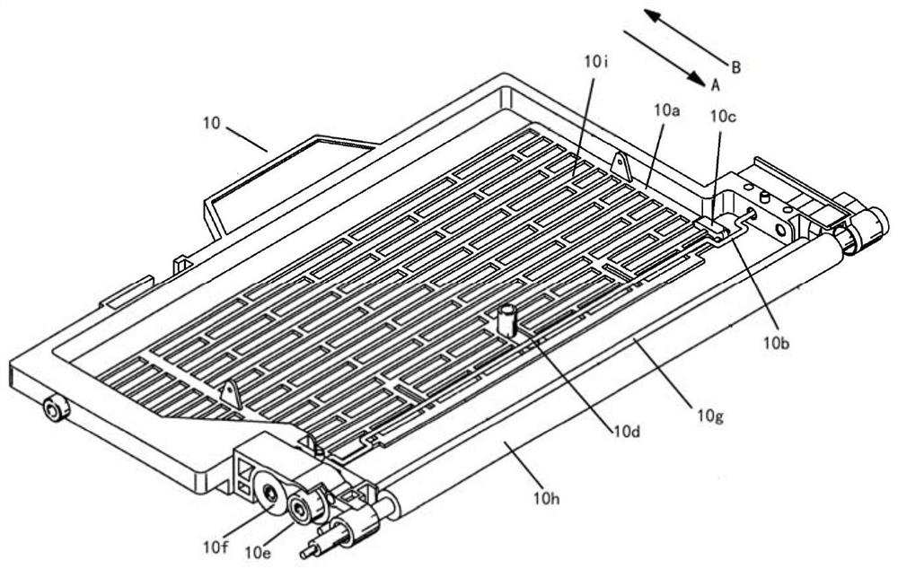
In addition, because this kind of agitator adopts linear reciprocating motion to realize the supply of developer, this method will not get sufficient stirring due to developer agitation, resulting in low developer supply efficiency and developer agglomeration, causing a large amount of developer Remains in the developer supply hopper, causing serious waste of developer

Method used


Image

  • A developing unit and a method for controlling the developing unit
  • A developing unit and a method for controlling the developing unit
  • A developing unit and a method for controlling the developing unit

Examples


Embodiment Construction

[0053] The following embodiments of the present invention in conjunction with the accompanying drawings of the specification are described in further detail.

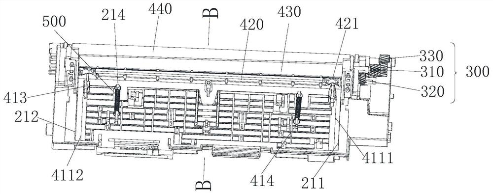
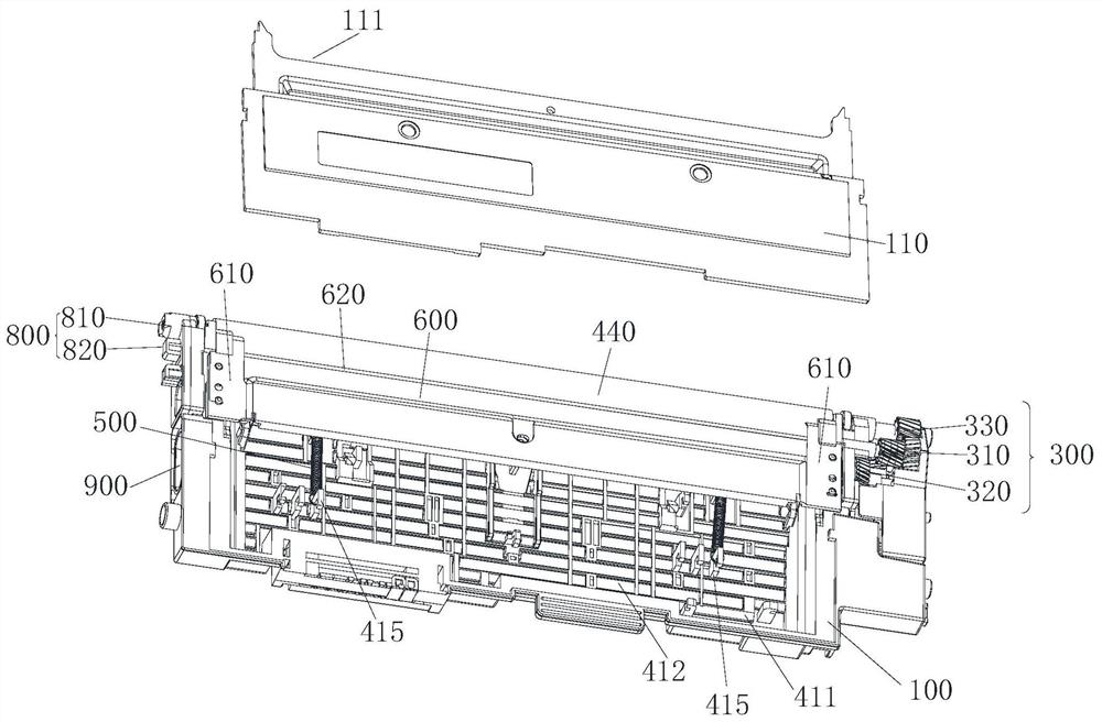
[0054] as Figure 2 - Figure 4 As shown, the present invention provides a development unit and a development unit control method, wherein the development unit comprises a box 100; Developer storage unit disposed on the cassette 100 for storing the developer; Disposed on the side of the box 100 of the development unit, the power unit 300 for receiving the driving force provided by the imaging apparatus body and the supply unit. The supply unit is installed in the developer storage unit 210 provided in the developer storage unit. Wherein the supply unit comprises a stirring unit 411, the mixing unit 411 is a roughly rectangular frame-like plate structure, the stirring unit 411 is provided with a pore-like structure, the pore-like structure is preferably at least one through hole 412, at least one through hole 412 along the len...


PUM


Abstract

The invention discloses a development unit and a control method for the development unit. The development unit includes a box body, a developer storage unit is arranged on the box body, and has a developer storage cavity for storing developer; a power unit is arranged in the development unit. One side is used to receive the driving force provided by the main body of the imaging device; the supply unit is arranged in the developer storage unit and is used for supplying the developer. The supply unit includes a stirring unit, which is provided with a hole-like structure, and the stirring unit receives The driving force provided by the power unit is used to periodically rotate in a way that first raises and then lowers relative to the bottom plate of the developer storage unit for supplying the developer. The structural design of the developing unit provided by the present invention has the advantages of high developer supply efficiency and less developer residue, avoiding waste of developer, in addition, it also has high developer storage capacity, simplified mechanical structure, and satisfies the miniaturization of imaging devices needs and other advantages.

Description

Technical field [0001] The present invention relates to the technical field of the development unit in the imaging apparatus, in particular to a development unit and a development unit control method. Background [0002] Typically, electronic imaging devices such as printers, photocopiers, fax machines and multifunction peripherals (MFPs) can form an image on the print medium based on the input image signal. First, the use of charging roller to the surface of the photosensitive medium to apply bias pressure, so that it is charged to the predetermined potential, the exposure unit will be corresponding to the image signal data modulation light scanning to the surface of the photosensitive medium to form an electrostatic latent image, the developer stored in the developer supply silo through the agitator friction charged, the supply roller will be charged developer to the development roller, the developer layer attached to the surface of the developer roller under the action of the ...

Claims


Application Information

Patent Timeline
Patent Type & Authority Patents(China)
IPC IPC(8): G03G15/08G03G21/16
CPCG03G15/0889G03G15/0891G03G15/0896G03G21/1647G03G15/0877
Inventor 罗琴
Owner NINESTAR CORP
Learn More