Bearing device and method of manufacturing the bearing device

a bearing device and rolling bearing technology, applied in the direction of mechanical equipment, transportation and packaging, rigid support of bearing units, etc., can solve the problem of minute cracks on the caulked portion, and achieve the effect of improving the supply rate of bearing devices

Inactive Publication Date: 2010-04-06
JTEKT CORP
View PDF4 Cites 0 Cited by
  • Summary
  • Abstract
  • Description
  • Claims
  • Application Information

AI Technical Summary

Benefits of technology

[0006]Preferably, at least in the end portion of the shaft body, the average value of the layer gaps of the cementite is set in a range from not less than 0.15 μm to not more than 0.4 μm. The inventors have found that the generation of minute cracks is caused by the existence of cementite in the pearlite, and based upon this fact, have set the average value of the layer gaps of cementite to the above-mentioned range. With this arrangement, even when the end portion of the shaft body is caulked onto the bearing ring, the rate of occurrence of the minute cracks on its end portion is reduced to zero. Thus, it becomes possible to improve the supply rate of the bearing device as a product.

Problems solved by technology

When the end portion of the hub shaft is caulked onto the end face of the inner ring bearing element, minute cracks tend to occur on the caulked portion.

Method used


Image

  • Bearing device and method of manufacturing the bearing device
  • Bearing device and method of manufacturing the bearing device
  • Bearing device and method of manufacturing the bearing device

Examples


Embodiment Construction

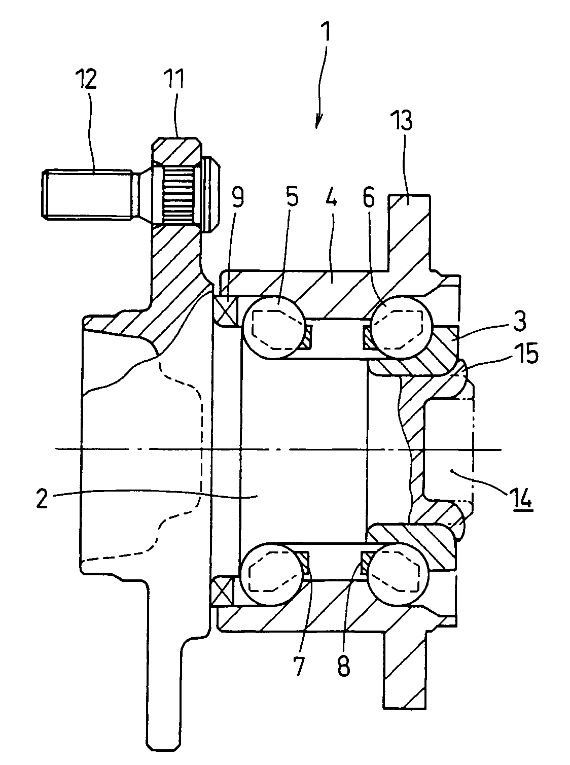
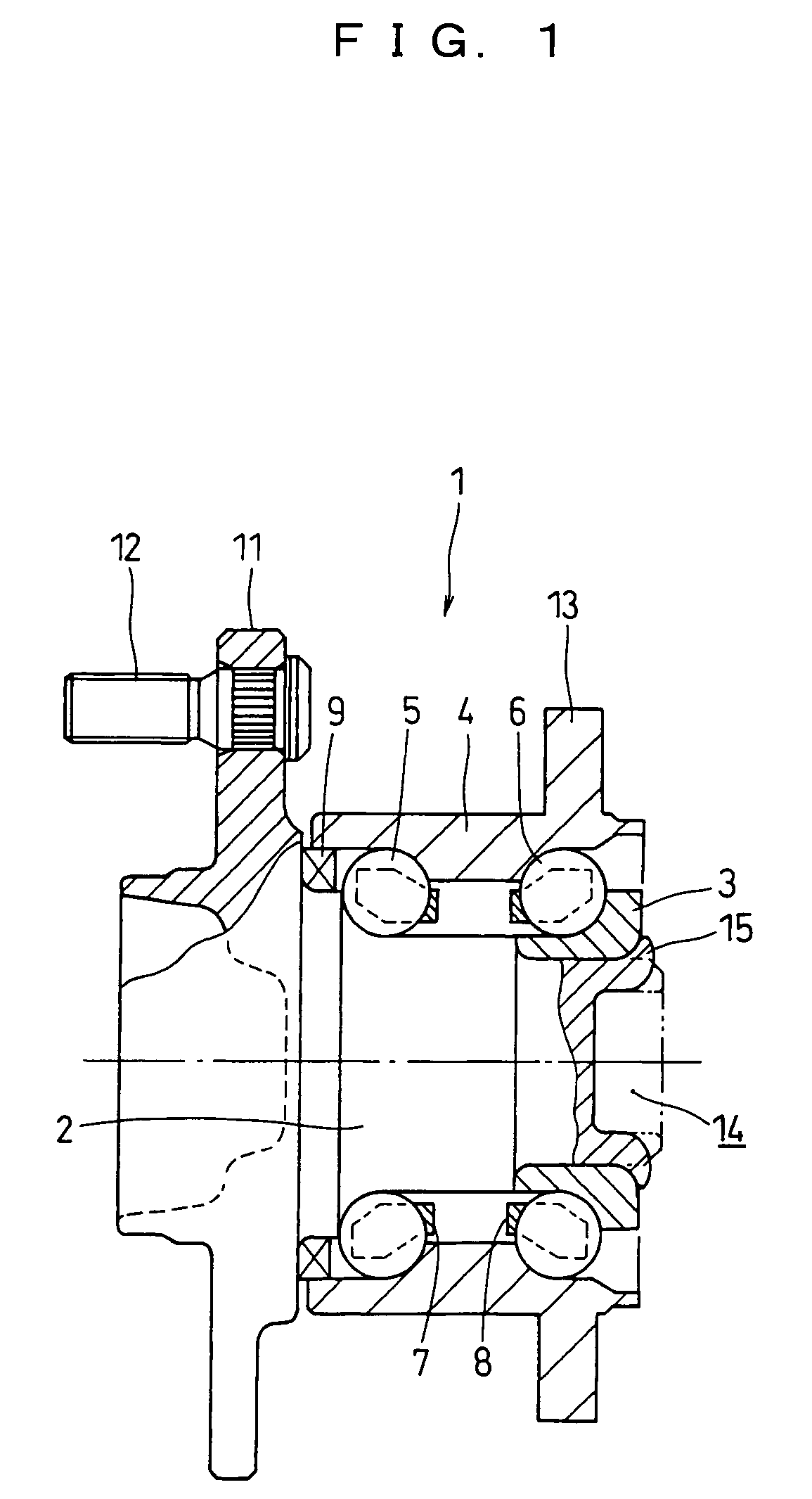
[0016]Referring to drawings, the following description will discuss a rolling bearing device in accordance with a preferred embodiment of the present invention in detail. A rolling bearing device applied to a bearing for a vehicle axle, more specifically, a rolling bearing device on the driven wheel side will be explained. FIG. 1 is a cross-sectional view illustrating the entire structure of the rolling bearing device, FIG. 2 is an enlarged cross-sectional view of a caulked portion, FIGS. 3(a) to 3(f) are schematic cross-sectional views illustrating the composition of the caulked portion, and FIG. 4 is an enlarged view illustrating the composition of pearlite. In FIG. 1, the right side in the axial direction shows a vehicle inner side, and the left side in the axial direction shows a vehicle outer side.

[0017]With respect to bearing rings that are placed radially inside and outside of a double row angular contact ball bearing with vertex of contact angles outside of bearing, a rollin...


PUM

PropertyMeasurementUnit
temperatureaaaaaaaaaa
structureaaaaaaaaaa

Abstract

A bearing device is provided with a bearing ring and a shaft body that is made of carbon steel including pearlite having a cementite layer structure, and has an end portion caulked onto the bearing ring, and in this device, at least in the end portion of the shaft body, the layer gap of the cementite in the pearlite is made greater.

Description

FIELD OF THE INVENTION[0001]The present invention relates to a rolling bearing device that is preferably applied to, for example, an axle and the like of a vehicle, and also relates to a manufacturing method thereof.BACKGROUND OF THE INVENTION[0002]The rolling bearing device for an axle is generally provided with an outer ring member that is attached to the vehicle body side and an inner ring member that is rotatably supported on the outer ring member so as to freely rotate around the bearing axis through two rows of rolling elements. This inner ring member is constituted by a hub shaft to which a wheel is attached and an inner ring bearing element that is fitted to the end portion of this hub shaft. The end portion of the hub shaft is deformed radially-outward to be caulked onto the end face of the inner ring bearing element so that the hub shaft is rotatably integrated with the inner ring bearing element. The hub shaft of this type is generally made of a steel material such as car...

Claims


Application Information

Patent Timeline
Patent Type & Authority Patents(United States)
IPC IPC(8): F16C33/32B21D53/10B23P17/00F16C13/00B60B27/00F16C19/18F16C19/38F16C35/063F16C43/04
CPCB60B27/00B60B27/0005B60B27/001B60B27/0084B60B27/0094F16C35/063F16C43/04C21D2211/003Y10T29/49636F16C19/187F16C19/386F16C19/186C21D2211/009F16C2326/02
Inventor TODA, KAZUTOSHIKASHIWAGI, SHINICHIROUTOMITA, DAISAKU
Owner JTEKT CORP
Why Eureka
Try Eureka