
Spark plug for internal combustion engines

a technology for spark plugs and internal combustion engines, which is applied in the direction of spark plugs, basic electric elements, electric devices, etc., can solve the problems of affecting the stability of combustion, and affecting the ignitability of spark plugs, so as to prevent the stagnation of airflow f, stable ignitability, and the effect of reducing the stagnation ra

Active Publication Date: 2015-02-24
DENSO CORP
View PDF9 Cites 0 Cited by
  • Summary
  • Abstract
  • Description
  • Claims
  • Application Information

AI Technical Summary

Benefits of technology

The patent describes a spark plug design that prevents airflow blockages and ensures stable ignitability. It achieves this by using baffle projections on the electrodes that direct the airflow towards the spark discharge gap and prevent it from being blocked. This ensures a discharge spark that can extend to a large extent and ignite the air-fuel mixture effectively. The design is simple and does not require complex shaping of the ground electrode. Overall, the patent provides a solution for improving the performance of spark plugs in combustion engines.

Problems solved by technology

As a result, the ignitability of the spark plug may be impaired.
In other words, depending on the mounting posture of the spark plug with respect to the internal combustion engine, the ignitability of the spark plug may be problematically varied.
In such an internal combustion engine, combustion stability may be impaired depending on the mounting posture of the spark plug.
Further, it is difficult to control the mounting posture of the spark plug with respect to the internal combustion engine, i.e. to control the position of the ground electrode in the circumferential direction of the spark plug.
This is because the mounting posture of the spark plug is unavoidably varied, depending such as on the state of the mounting screws formed in the housing, or the degree of tightening the spark plug in the work of mounting the spark plug on the internal combustion engine.
However, the “configuration in which the ground electrode is drilled to form a hole therein” as disclosed in the patent document JP-A-H09-148045 may weaken the strength of the ground electrode.
If the ground electrode is thickened to recover the weakened strength, the thickened ground electrode after all may tend to block the flow of the air-fuel mixture.
Further, the “configuration in which the ground electrode is joined to the housing using a plurality of thin-plate members” as disclosed in the patent document JP-A-H09-148045 may complicate the shape of the ground electrode and the number of manufacturing steps may be increased, leading to the problem of increasing the manufacturing cost.
In this situation, the force of the airflow passing through the spark discharge gap tends to be weakened and the discharge spark is unlikely to be extended to a large extent.
Therefore, when a part of the ground electrode is located downstream of the spark discharge gap, the ignitability is likely to be comparatively impaired.

Method used


Image

  • Spark plug for internal combustion engines
  • Spark plug for internal combustion engines
  • Spark plug for internal combustion engines

Examples


experimental example 1

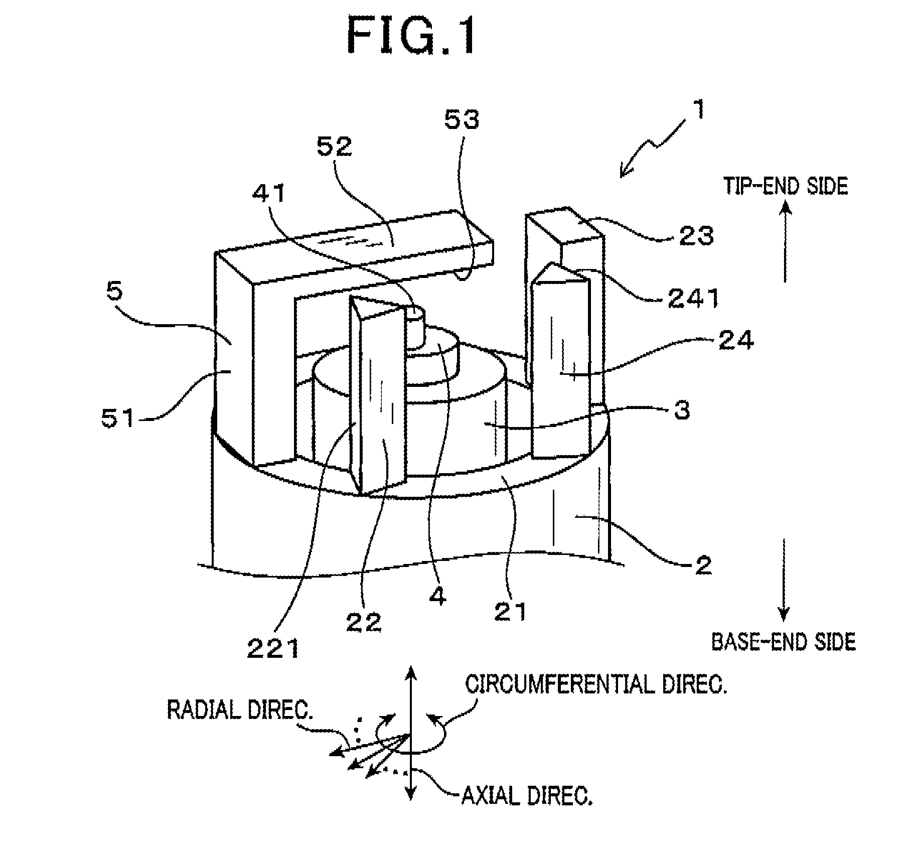
[0123]As shown in FIG. 13, in Experimental Example 1, the spark plugs 1, 9 and 90 of the first embodiment, Comparative Example 1 and Comparative Example 2, respectively, were used to investigate how the A / F limit varied depending on the location of the vertical portions 51 and 951 of the ground electrodes 5 and 95, respectively, with respect to the airflow F.

[0124]Specifically, the A / F limit was measured by changing a mounting angle β in increments of 90° in a range of 0° to 360°. The mounting angle β is an angle between the direction of entry of the airflow F into the spark plug 1 and the radial direction connecting between the circumferential position of the vertical portion 51 of the ground electrode 5 and the center axis of the spark plug 1, when the spark plug 1 of the first embodiment is viewed in the axial direction from the tip-end side. More specifically, when the mounting angle β is 0°, the vertical portion 51 of the ground electrode 5 is located upstream of the spark disc...


PUM


Abstract

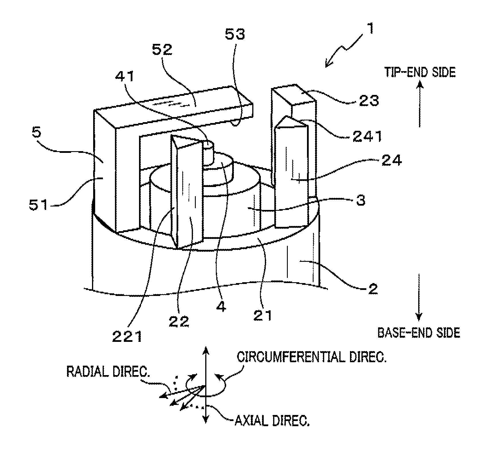
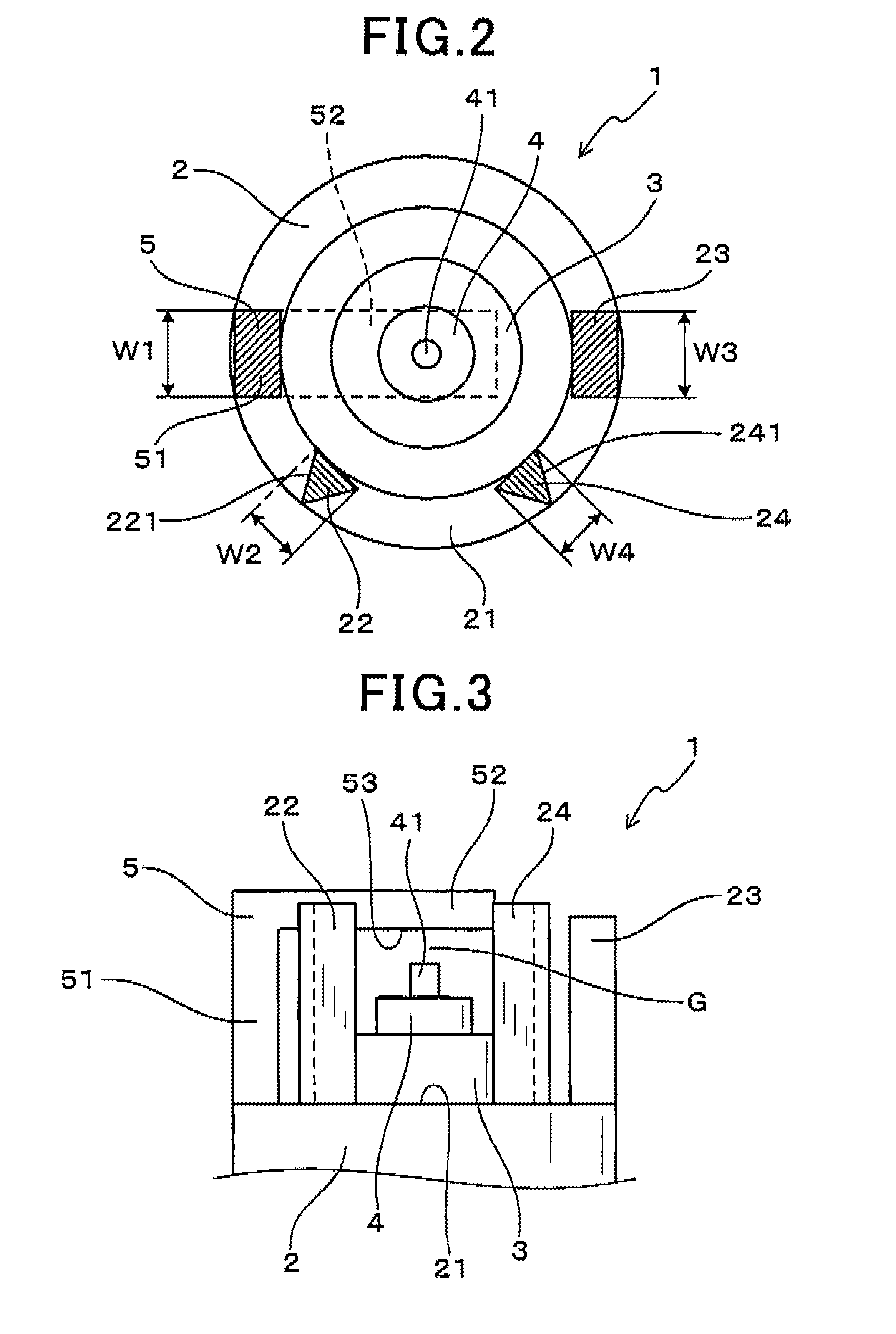
A spark plug for internal combustion engines is provided, where the spark plug includes a cylindrical housing, a cylindrical insulation porcelain part, a center electrode, and a ground electrode. The insulation porcelain is housed in the housing and the center electrode is held inside the insulation porcelain. The ground electrode protrudes from a top end portion of the housing. A spark discharge gap is left between the ground and center electrodes. Further, first to third projections are formed on the top end portion. The first projection is opposed to the ground electrode with the center electrode therebetween. The second projection is closer to the ground electrode than to the first projection. The third projection is closer to the first projection than to the ground electrode.

Description

CROSS-REFERENCE TO RELATED APPLICATION[0001]This application is based on and claims the benefit of priority from earlier Japanese Patent Application No. 2012-269106 filed Dec. 10, 2012, the description of which is incorporated herein by reference.BACKGROUND OF THE INVENTION[0002]1. Technical Field of the Invention[0003]The present invention relates to a spark plug for internal combustion engines which are mounted in structures such as vehicles.[0004]2. Related Art[0005]Spark plugs are used as igniting means in internal combustion engines, such as the engines for vehicles. Some of such spark plugs have a configuration in which a center electrode is permitted to axially face a ground electrode to form a spark discharge gap therebetween. This type of spark plug causes discharge in the spark discharge gap to use the discharge for the ignition of the air-fuel mixture in the combustion chamber.[0006]In the combustion chamber, a flow of the air-fuel mixture, such as a swirl flow or a tumbl...

Claims


Application Information

Patent Timeline
Patent Type & Authority Patents(United States)
IPC IPC(8): H01T13/20H01T13/02
CPCH01T13/02H01T13/32
Inventor SHIBATA, MASAMICHIINOHARA, TAKAYUKIOKABE, SHINICHIAOCHI, TAKANOBUDOI, KAORI
Owner DENSO CORP
Learn More