
Device for transporting small volumes of a fluid, in particular a micropump or microvalve

a technology of fluid transport device and micro-fluidic device, which is applied in the direction of positive displacement liquid engine, machine/engine, laboratory glassware, etc., to achieve the effect of minimizing disadvantag

Active Publication Date: 2015-02-10
THINXXS MICROTECHNOLOGY AG
View PDF14 Cites 17 Cited by
  • Summary
  • Abstract
  • Description
  • Claims
  • Application Information

AI Technical Summary

Benefits of technology

The present invention is a novel transporting device that improves on previous devices by making them more economical and simple. The device has a tight fluid transporting duct that can handle high pressure, and a front film that can be determined to ensure constant flow. The device also has an additional film that creates a controlled pressure space to minimize variations in the pressure of the fluid.

Problems solved by technology

With respect to achieving a mass production which is economical but still meets high precision requirements, this gives rise to a multitude of specific problems, which in many cases prevent further reduction of the costs and the manufacture of synthetic microfluidic chips as disposable products.

Method used


Image

  • Device for transporting small volumes of a fluid, in particular a micropump or microvalve
  • Device for transporting small volumes of a fluid, in particular a micropump or microvalve
  • Device for transporting small volumes of a fluid, in particular a micropump or microvalve

Examples


Embodiment Construction

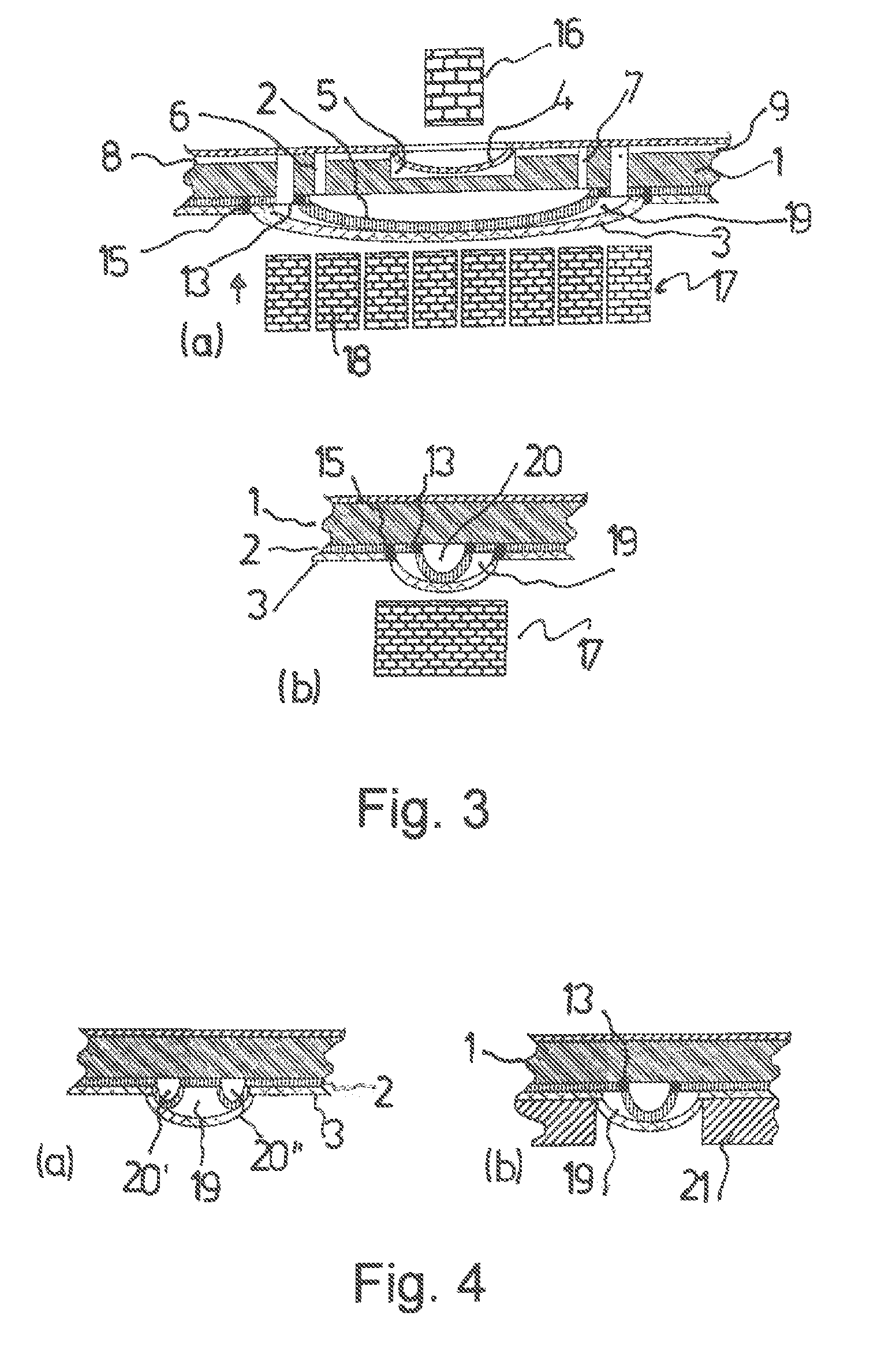
[0038]A structural micropump group illustrated in FIGS. 1 to 4 comprises a substrate 1 in the form of a flat plate, a film 2 connected to the plate side of the substrate 1, and another film 3 connected to the substrate 1 through the film 2. On its side facing away from the films 2 and 3, the substrate 1 is connected to a third film 4.

[0039]In the illustrated embodiment, all of the mentioned components are of the same synthetic material. To be considered in this connection are, for example, PMMA, PC, PS, PP, PE, COC, COP, PET or PEEK.

[0040]The thickness of the substrate 1 may be, for example, between 0.5 mm and 5 mm, in particular between 0.5 mm and 2 mm. The thickness of the film 2 is preferably in the range of 0.001 mm to 0.5 mm, particularly 0.01 mm to 0.1 mm and the thickness of the film 3 is, for example, 0.01 mm to 1 mm, preferably 0.05 mm to 0.3 mm.

[0041]While the films 2 and 3 extend in the illustrated embodiment beyond the entire plate surface of the substrate 1, the film 4 ...


PUM


Abstract

A microfluidic device for transporting a fluid, in particular a micropump or microvalve. The device has films, which lie against each other at film surfaces facing each other and are connected to each other in such a way that a transport channel to be formed between the films is defined, Deflecting apparatuses for forming the transport channel by jointly deflecting the films lie against each other in a direction perpendicular to the film surfaces. A deflecting surface region of the rear film in the deflection direction lies within the deflecting surface region of the front film in the deflection direction defined by the connection between the films.

Description

[0001]The present application is a 371 of International application PCT / DE2011 / 050017, filed May 31, 2011, which claims priority of DE 10 2010 022 550.9, filed Jun. 2, 2010 and DE 10 2011 015 184.2, filed Mar. 26, 2011, the priority of these applications is hereby claimed and these applications are incorporated herein by reference.BACKGROUND OF THE INVENTION[0002]The invention relates to a device for transporting small volumes of a fluid, particularly a micropump or a microvalve.SUMMARY OF THE INVENTION[0003]Accordingly, the invention relates to the field of microfluidics, which is increasingly gaining significance in medicine and other biological sciences. Miniaturized devices for the analysis and / or material synthesis accommodated on a chip are increasingly used in diagnostics as well as in therapy. In particular, micropumps play an increasing role in medicament dosing.[0004]The transport device mentioned above can be considered to be used as a separate device or as a component of...

Claims


Application Information

Patent Timeline
IPC IPC(8): F16K51/00B01L3/00F04B43/02F04B43/04F16K99/00F17D1/00F17D1/08
CPCF17D1/08B01L3/50273B01L3/502738F04B43/021F04B43/043F16K99/0005F17D1/00B01L2300/0816B01L2300/0887B01L2400/0481B01L2400/0638F16K2099/008F16K2099/0084Y10T137/206Y10T137/2202Y10T137/2224Y10T137/598Y10T137/85938
Inventor WEBER, LUTZNEUMEIER, MICHEL
Owner THINXXS MICROTECHNOLOGY AG
Learn More