
Insulated panel and method of assembly

a technology of insulated panels and insulating panels, which is applied in the direction of furniture joining, sheet joining, material gluing, etc., can solve the problems of high investment cost, increased transportation cost, and cabinet containmen

Inactive Publication Date: 2015-02-03
ELECTROLUX HOME PROD PTY LTD
View PDF16 Cites 72 Cited by
  • Summary
  • Abstract
  • Description
  • Claims
  • Application Information

AI Technical Summary

Benefits of technology

The present invention provides an insulated panel with first and second panels that are spaced apart by a predetermined distance. The panel includes an intermediate joining member that connects to the peripheral flanges or edges of the first and second walls. The joining member can be an elongated profiled member or at least one slot or channel that engages with the edges of the walls. The joining member can be attached to the walls by adhesive, such as double-sided foamed tape. The panel can also include foam or other insulating material between the walls. The invention also provides a method of manufacturing the insulated panel, as well as a cabinet or appliance assembled from the panel. The technical effects of the invention include improved insulation, reduced weight, and improved durability of the insulated panel.

Problems solved by technology

The manufacture of cold appliance is commonly done close to the customers because of the bulky nature of the appliances, a large proportion of the volume being empty space.
This increases the cost of transportation.
A further complication is that the cabinet must contain technical equipment for performing different functions.
Another problem associated with the manufacturing of cold appliances is that it involves high investment costs for the development of product lines and the like.
Conventional manufacturing plants for cold appliances are usually inflexible, so that it is difficult to adapt the plant for manufacturing cold appliances with differing dimensions and variable component options in small series.
Thus the developers are discouraged from innovation, or variations in product design are very costly.
However, this can be problematic where foamed-in brackets and reinforcements are required, as improper location of these elements can result in a high scrap rate.
Further, it is difficult to incorporate vacuum insulation panels in a continuous line process.
It is also difficult to incorporate roll forming of steel panels into a continuous line process.

Method used


Image

  • Insulated panel and method of assembly
  • Insulated panel and method of assembly
  • Insulated panel and method of assembly

Examples


Embodiment Construction

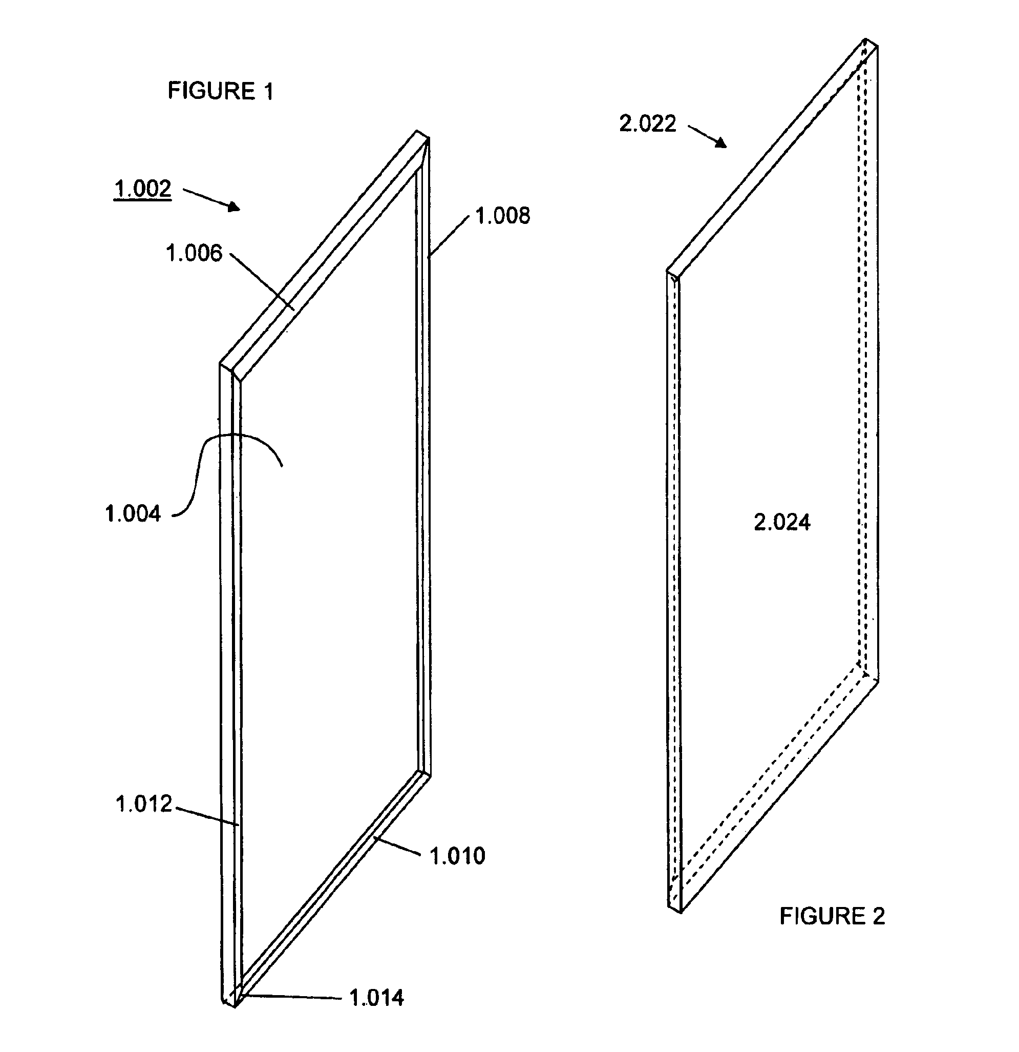
[0072]FIG. 1 illustrates an internal wall arrangement 1.002 including a major wall panel 1.004, the edges of which have been folded to form a shallow open box with a peripheral channel with attachment flanges 1.006, 1.008, 1.010, 1.012. The corners of the flanges can be mitred as shown, for example, at 1.014.

[0073]A second wall arrangement 2.022 is illustrated in FIG. 2 for assembly with the panel wall 1.002 of FIG. 1. The wall arrangement 2.022 can be a mirror image of the rear wall arrangement 1.002 of FIG. 1. Because the walls are symmetric, the wall arrangements 1.002, 2.022 can be identical, to reduce inventory. The panels are assembled with the peripheral channels facing each other. As discussed below, a joining member is used to connect the channel of the two panels. The walls can be roll formed and transported as a flat-pack.

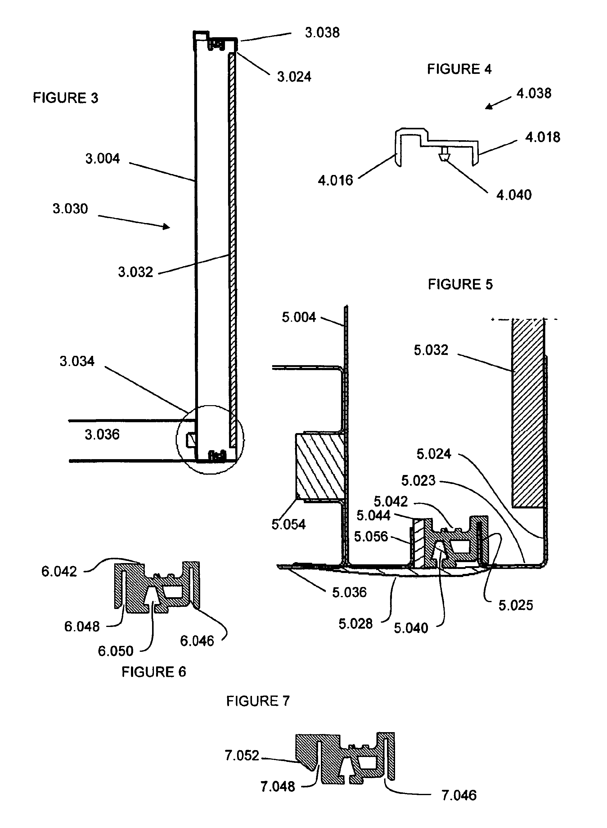
[0074]FIG. 3 illustrates a section of a panel assembly including a panel 3.030 formed by the front wall 3.024 and rear wall 3.004 such as those of FIGS....


PUM


Abstract

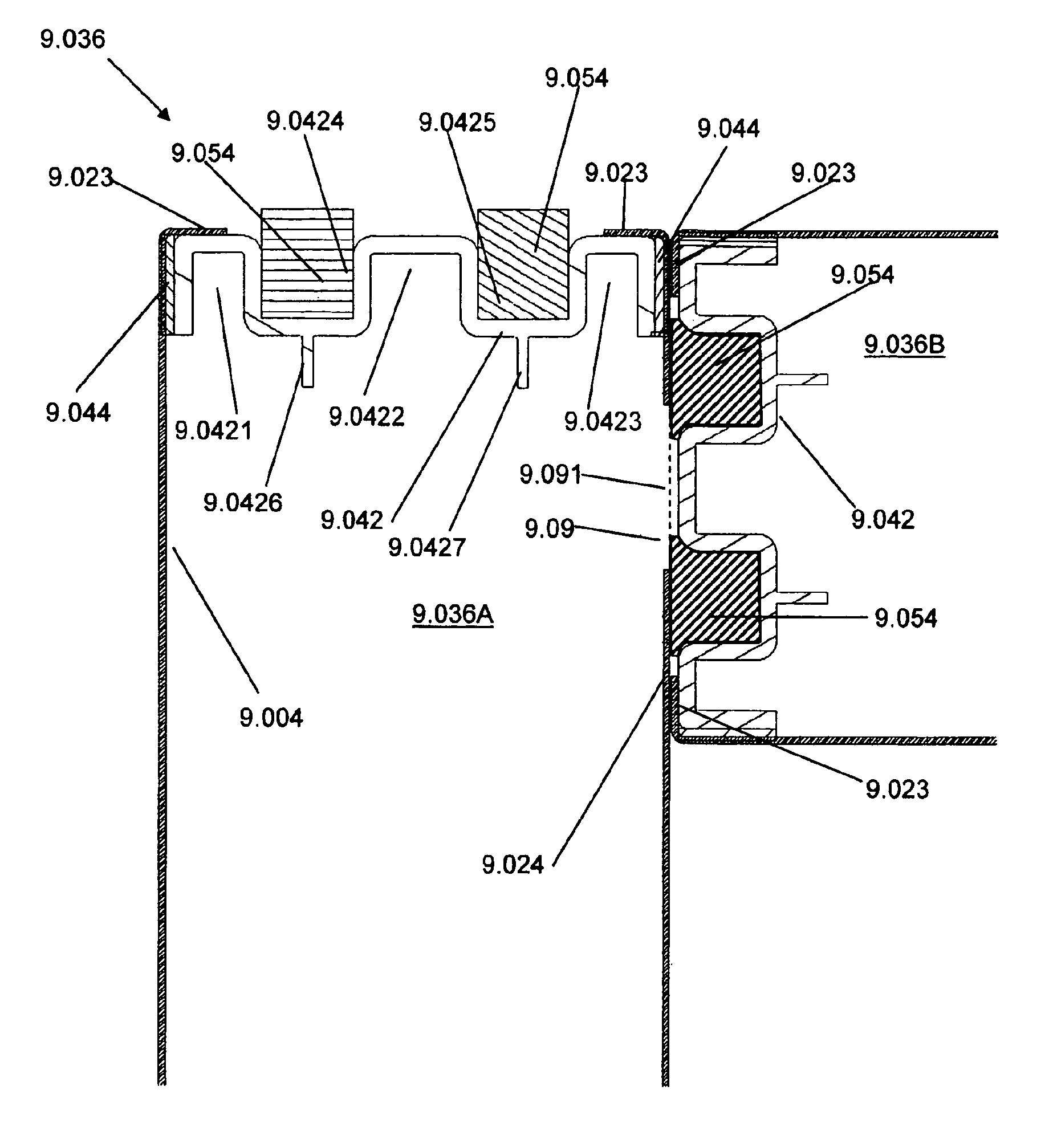
An insulated panel including first and second walls (5.004, 5.024) spaced apart by a predetermined distance, each wall including an internal peripheral channel formed by first and second bends, the second bend forming an internal peripheral flange (5.025, 5.056), the panel including an intermediate joining member (5.042) adapted to connect to the internal peripheral flanges of the first and second walls. The connection to a first flange can be via a slot (6.046), and the connection to the second flange can be by adhesive (5.044).

Description

FIELD OF THE INVENTION[0001]This invention relates to insulated panels and a method of assembling insulated panels.[0002]The invention is particularly suited for insulated panels for cold apparatus such as, for example, refrigerators, freezers, refrigerator and freezer combinations, wine coolers, wine cabinets, side by side, multi door and undercounter refrigerators etc.BACKGROUND OF THE INVENTION[0003]The manufacture of cold appliance is commonly done close to the customers because of the bulky nature of the appliances, a large proportion of the volume being empty space. This increases the cost of transportation. The cabinet must be easily assembled to form a rigid structure with good thermal insulation characteristics, and to resist moisture migration, and must have an aesthetically attractive appearance. A further complication is that the cabinet must contain technical equipment for performing different functions. In particular, the cold appliance must have a refrigeration system...

Claims


Application Information

Patent Timeline
Patent Type & Authority Patents(United States)
IPC IPC(8): E04B2/56A47F3/04E04B2/60F16B5/00F16B5/06F16B5/12F16B11/00F25D23/08
CPCF16B5/00E04B2/56F25D23/085E04B2/60A47F3/0482F16B5/0635F16B5/128F16B11/006Y10T403/473
Inventor SANDERS, PHILIPCHITRE, ROHITANWAR, MOHAMMED
Owner ELECTROLUX HOME PROD PTY LTD
Learn More