
Implantable electrode lead

a technology of electrode lead and electrode elongation, which is applied in the direction of internal electrodes, transvascular endocardial electrodes, therapy, etc., can solve the problems that patients with cardiac pacemakers the electric lead thereof can heat up in nuclear, and the patient's cardiac pacemaker typically cannot be examined in nuclear resonance tomographs. only to a limited exten

Inactive Publication Date: 2015-01-27
BIOTRONIK SE & CO KG
View PDF5 Cites 4 Cited by
  • Summary
  • Abstract
  • Description
  • Claims
  • Application Information

AI Technical Summary

Benefits of technology

[0015]In both cases, the intended effect of reducing the heat development of these electrodes is based on the detuning of the antenna properties of the electrode lead, which are resonant for the MRT fields, either by way of a variation of length or geometry and / or by adding an inductor.
[0017]In both cases, an MRT-compatible electrode lead results which, after implantation, assumes a coiled shaped, either entirely or in part, and is therefore a poorly tuned antenna for the MRT-HF fields, thereby reducing the MRT-induced development of heat.

Problems solved by technology

Such electrode leads have the disadvantage that the electric lead thereof can heat up in a nuclear resonance tomograph because the alternating magnetic fields in the nuclear resonance tomograph induce notable electric currents in the electric conductor.
For this reason, patients with cardiac pacemakers typically cannot be examined in a nuclear resonance tomograph, or only to a limited extent.
Such supply leads contain electric leads required for the functions of the particular electrode lead and are therefore exposed to the risk that electric currents can be induced therein by external alternating magnetic fields, which can result, for example, in unwanted heating of the supply leads or the electrode poles connected thereto, or which can result in the output of corresponding currents by way of the electrode poles to surrounding tissue and, therefore, in heating of the surrounding tissue.

Method used


Image

  • Implantable electrode lead
  • Implantable electrode lead
  • Implantable electrode lead

Examples


Embodiment Construction

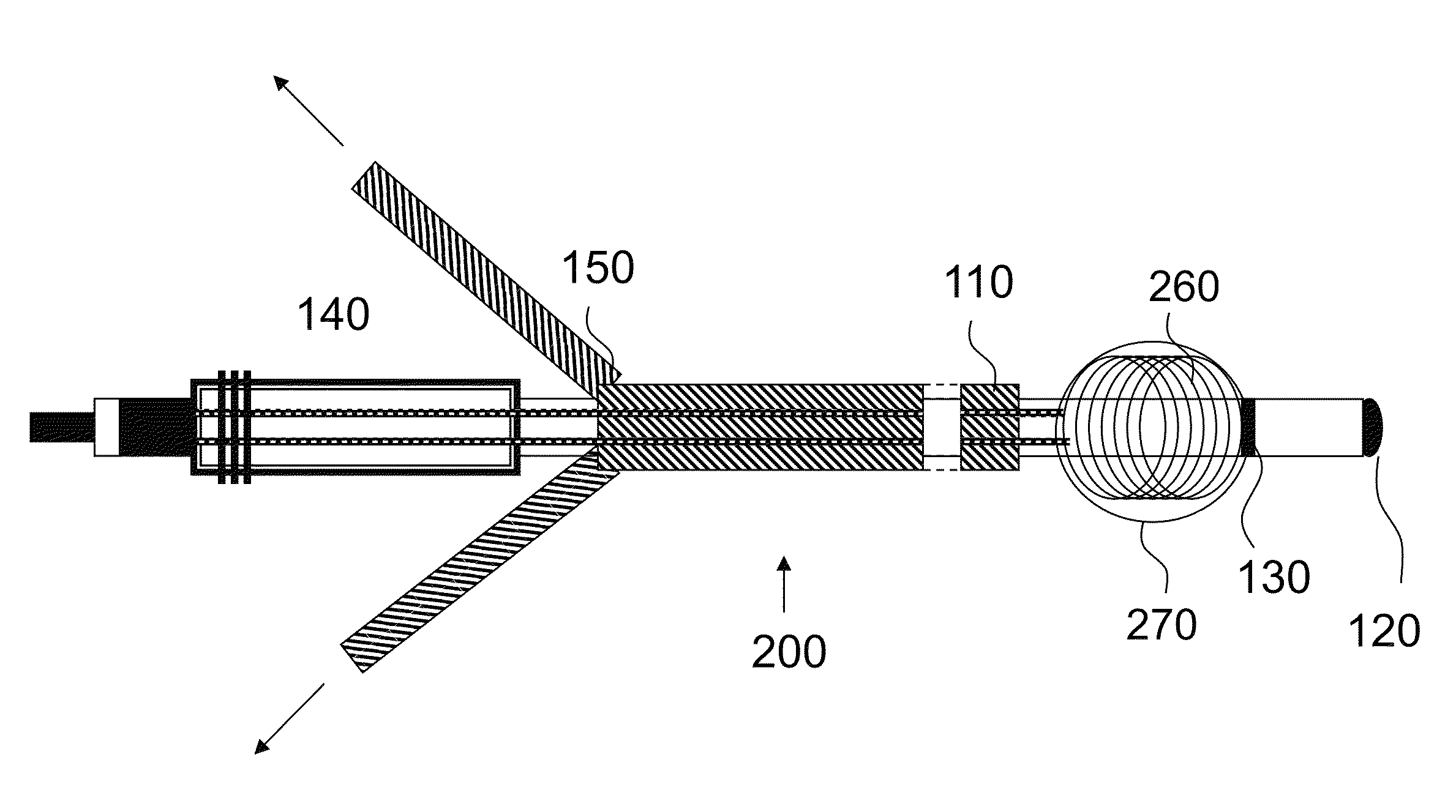
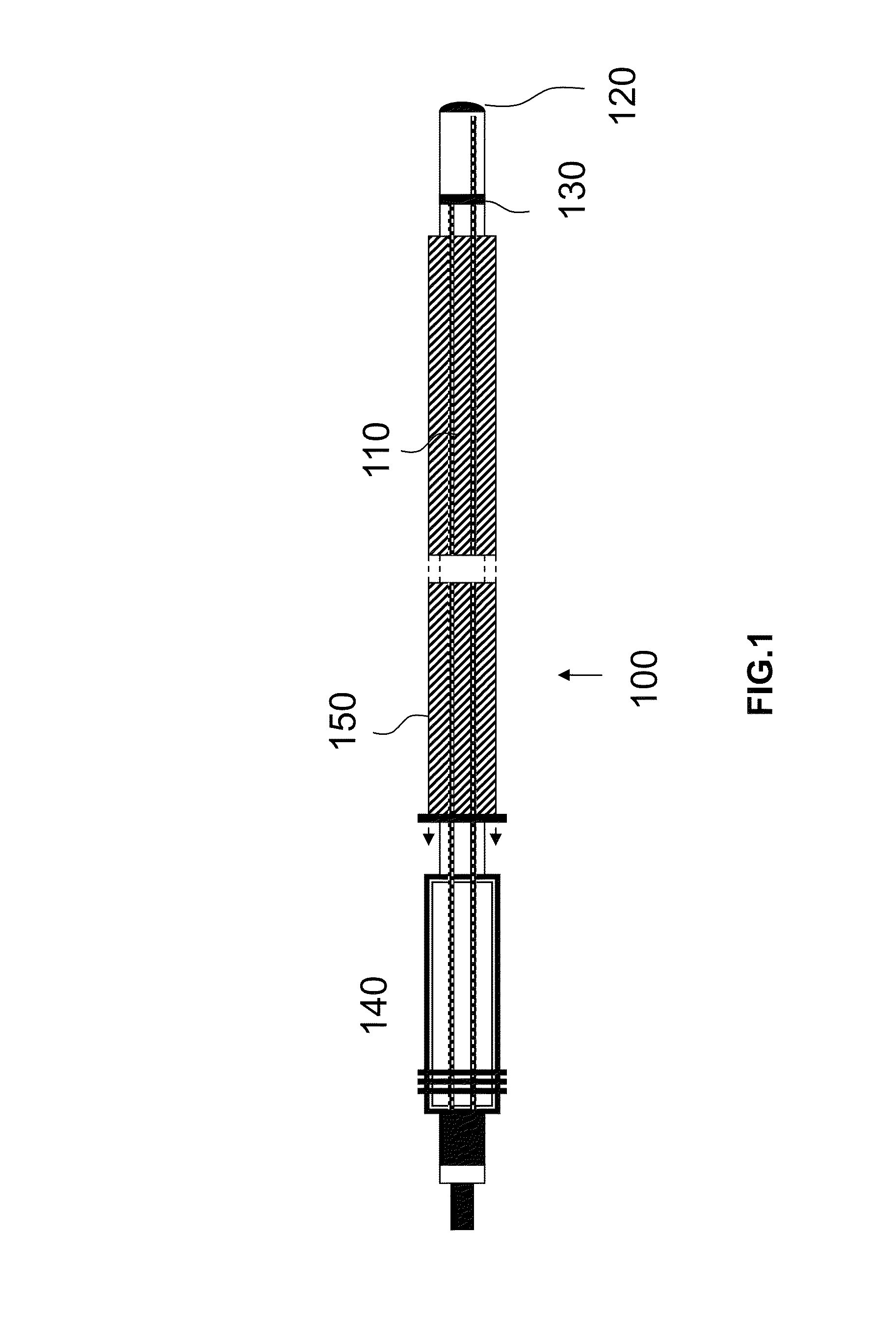
[0031]FIG. 1 shows an electrode lead 100 according to the invention, before implantation. The electrode lead 100 comprises an insulated supply lead 110 or jacket, a bipolar electrode pole (tip: 120, ring 130) and a corresponding connector or connecting plug 140 and an insertion aid 150 to be used temporarily, in order to create an elongated shape upon implantation. In the example shown, this insertion aid 150 is designed as an introducer sheath or tube over the electrode lead. Alternatively, however, a rigid stylet or a mandrel can be used.

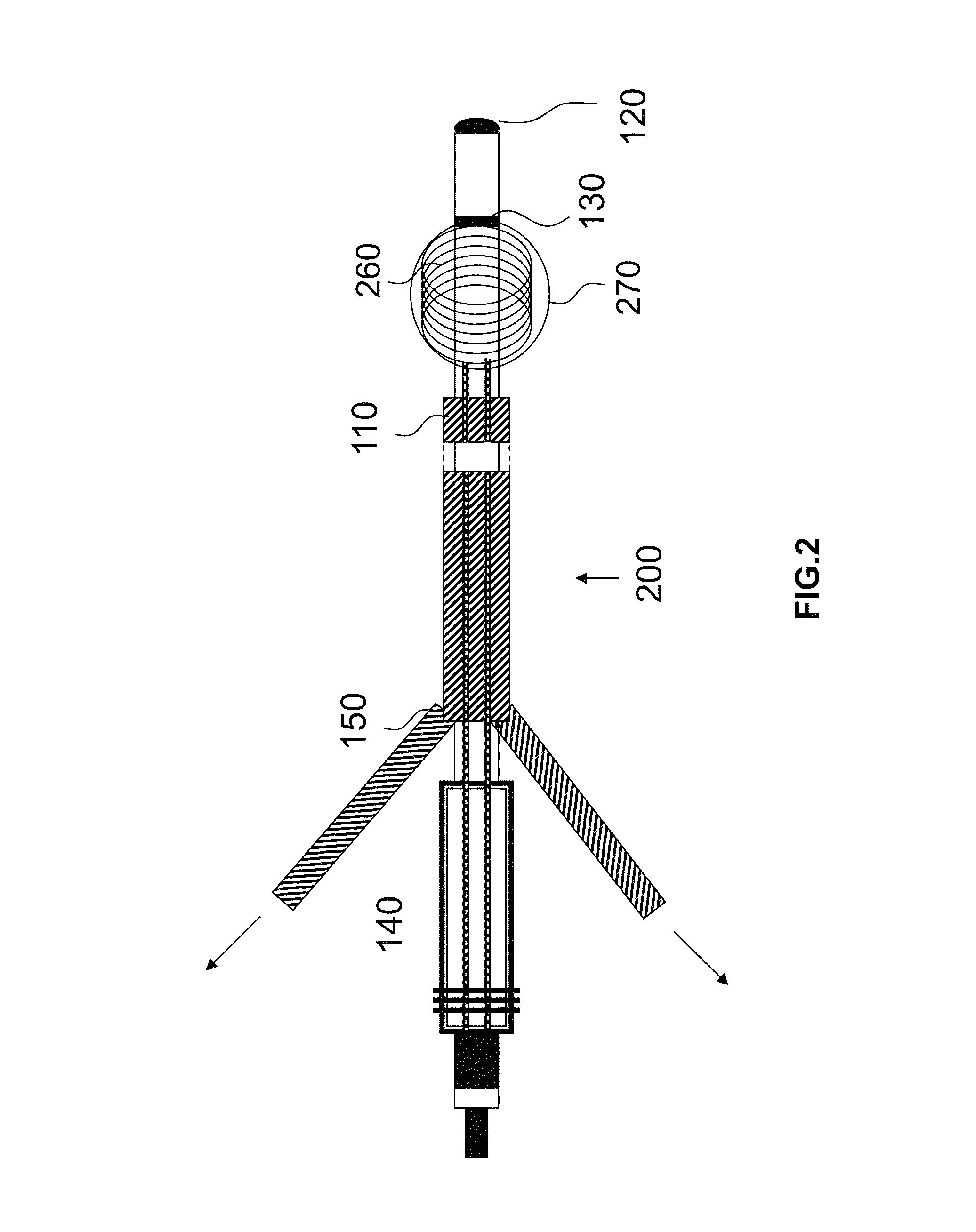
[0032]In FIG. 2, the electrode lead is shown upon completion of the implantation. In addition to the features stated in FIG. 1, a deformable supply lead section 260 of the electrode lead is now shown. In this embodiment, the deformable supply lead section forms a coil in the distal region of the electrode lead having a diameter of 3-15 mm. The altered shape of the deformable supply lead section 260 is induced either by way of a preformation of a j...


PUM


Abstract

An implantable electrode lead comprising an electric supply lead. The electric supply lead is designed to assume, after implantation of the electrode lead in a deformable supply lead section, a shape that is changed such that it induces higher inductance in the deformable supply lead section after deformation than before deformation, wherein the inductance is at least 0.1 μH. The implantable electrode lead can also comprise an outer sleeve within which the supply lead is disposed. The electric supply lead is designed to assume, after implantation of the electrode lead in a deformable supply lead section, a shape that has changed compared to the original shape thereof. The supply lead is also designed and disposed inside the sleeve such that the supply lead, in the deformable supply lead section thereof, is deformable relative to the outer sleeve and inside the outer sleeve.

Description

[0001]This application claims the benefit of U.S. Provisional Patent Application 61 / 568,182 filed on 8 Dec. 2011, the specification of which is hereby incorporated herein by reference.BACKGROUND OF THE INVENTION[0002]1. Field of the Invention[0003]At least one embodiment of the invention relates to an implantable elongated electrode lead.[0004]2. Description of the Related Art[0005]Electrode leads of are connected, for example, to implantable cardiac stimulators such as cardiac pacemakers, cardioverters, defibrillators or the like, and may also serve as mapping catheters for diagnosis or neurostimulation.[0006]Such electrode leads have the disadvantage that the electric lead thereof can heat up in a nuclear resonance tomograph because the alternating magnetic fields in the nuclear resonance tomograph induce notable electric currents in the electric conductor. For this reason, patients with cardiac pacemakers typically cannot be examined in a nuclear resonance tomograph, or only to a...

Claims


Application Information

Patent Timeline
Patent Type & Authority Patents(United States)
IPC IPC(8): A61N1/00A61N1/05A61N1/08A61N1/375
CPCA61N1/05A61N1/375A61N1/056A61N2001/086A61N1/086
Inventor DOERR, THOMASWEISS, INGO
Owner BIOTRONIK SE & CO KG
Learn More