
Method for automated measurement of the residual magnetic field strength of magnetized ferromagnetic workpieces

a technology of magnetized ferromagnetic workpieces and residual magnetic fields, which is applied in the direction of magnetisation measurements, magnetic measurements, and magnetic field measurement using galvano-magnetic devices, etc., can solve the problems of unsatisfactory magnetization, residual magnetic fields are very troublesome, and welding is difficult or even impossible, etc., to achieve quick, easy and reproducible results

Inactive Publication Date: 2015-01-27
VALLOUREC DEUT
View PDF5 Cites 0 Cited by
  • Summary
  • Abstract
  • Description
  • Claims
  • Application Information

AI Technical Summary

Benefits of technology

The invention provides a method for automatically measuring the residual field strength of magnetized ferromagnetic workpieces, such as pipes made of steel. This method is cost-effective, quick, easy, and reproducible, and can be used to determine the residual field strength at the end face of a pipe. The method can be easily incorporated into the structure of the pipe and is reliable in preventing damage to the measurement probes during pipe transport. The accuracy of the measurement can be enhanced by not limiting it to a single magnetic field component but using two components, namely, the radial and axial component. Additionally, the method can be effectively utilized even when applied external fields are expected during the measurement. The method involves using suitable shielding and filters in the signal path to eliminate the effects of external fields.

Problems solved by technology

However, an undesired magnetization can also occur during pipe manufacture, during further processing and when the pipes are transported.
These residual magnetic fields are very troublesome particularly in the vicinity of the pipe ends, because the arc generated when the pipes are welded together is adversely affected by these residual magnetic fields.
If the residual magnetic fields at the end face of the pipe ends are too strong, the arc is deflected, making welding difficult or even impossible.
This measurement process has the disadvantage that the measurement on the end face is quite difficult to automate at reasonable costs due to structural reasons.
However, these measurements are not very informative because a contacting measurement of the pipes would actually be required which, however, is typically omitted due to the high risk of damage by the passing pipe.
Moreover, a precisely defined distance to the end face of the pipe is very difficult to realize with moving pipes.
Variations of the signals can here not be unambiguously associated with changes in the residual field strength, because these variations could also be caused by an unintentional change of the spacing between the probe and the end face of the pipe.
The signal strength decreases significantly with increasing distance, which makes evaluation of the measurement results much more difficult.

Method used


Image

  • Method for automated measurement of the residual magnetic field strength of magnetized ferromagnetic workpieces
  • Method for automated measurement of the residual magnetic field strength of magnetized ferromagnetic workpieces
  • Method for automated measurement of the residual magnetic field strength of magnetized ferromagnetic workpieces

Examples


Embodiment Construction

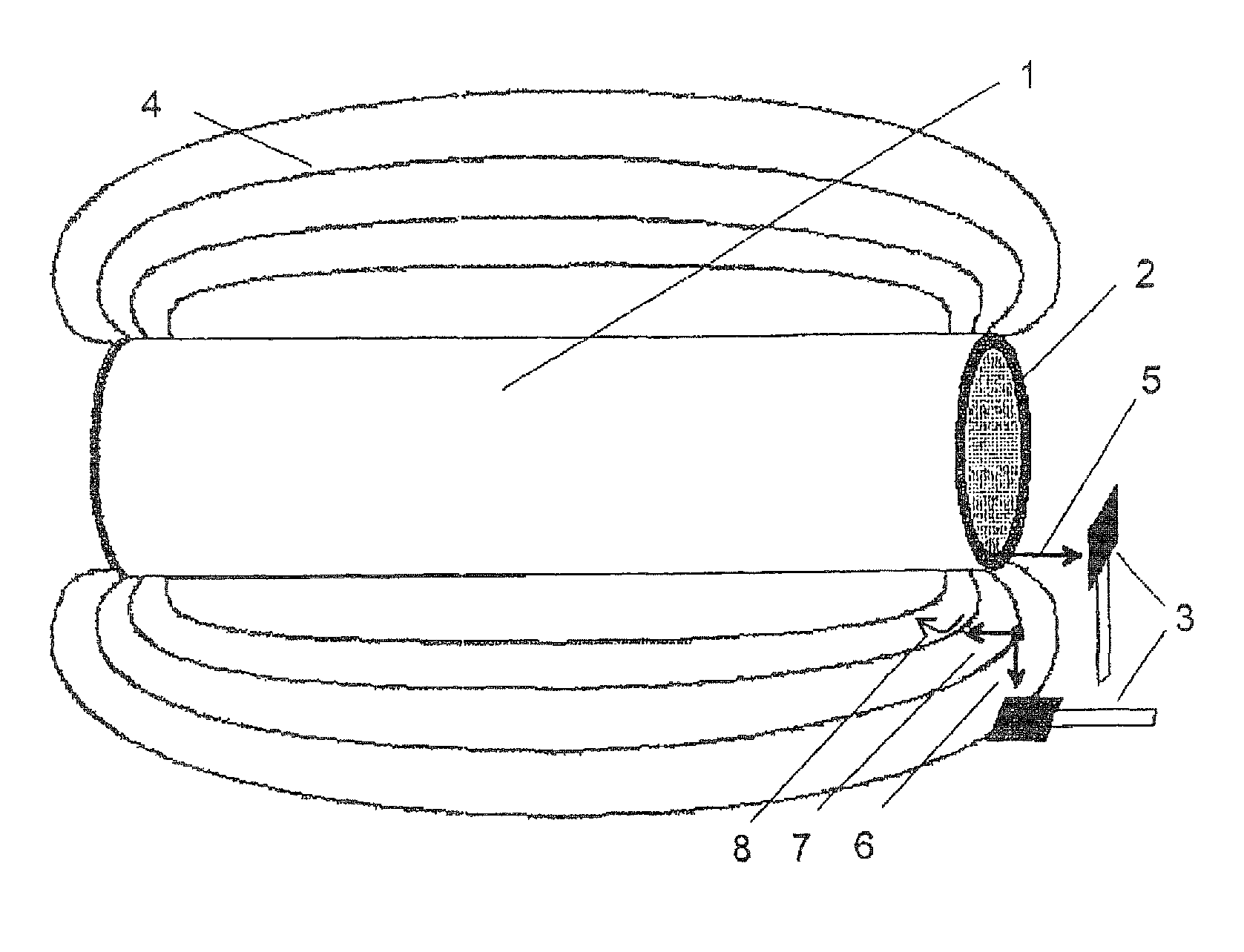
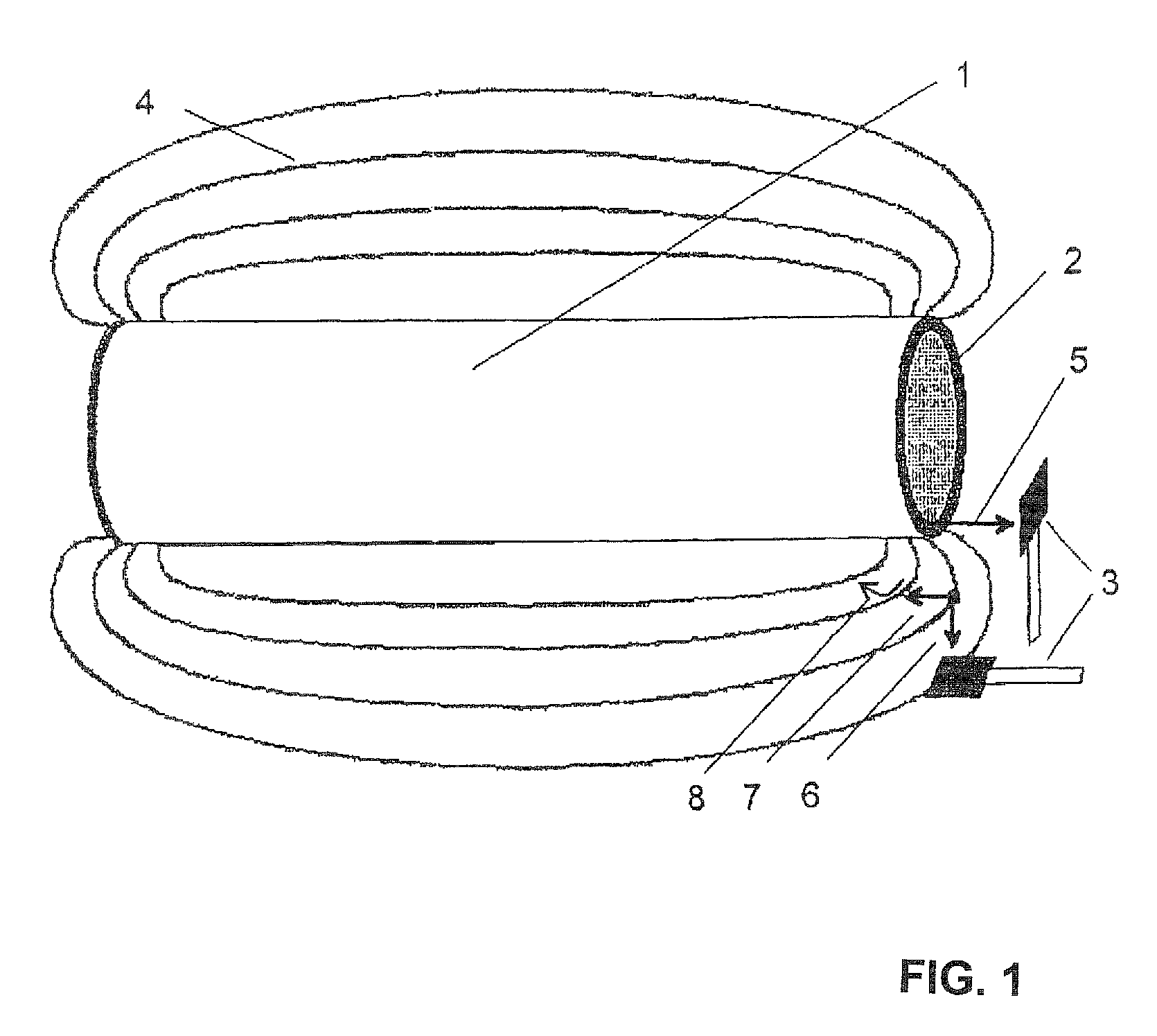
[0031]FIG. 1 shows in a schematic diagram an embodiment of the measurement method according to the invention for measuring the residual magnetic field strength on the pipe surface.

[0032]A pipe 1 has a residual magnetic field 4, which exits from the end face 2 of the pipe as an axially oriented magnetic field 5, wherein the axially oriented magnetic field 5 can according to the state-of-the-art in typical situations only be measured manually.

[0033]Because it is difficult to accurately measure the magnetic field at the end face during the pipe transport, the measurement according to the invention is now performed on the exterior pipe surface.

[0034]The measuring probe 3 is hereby arranged at a fixed location and at a defined distance from the exterior surface of the pipe 1, so that the residual magnetic field strength of the pipe 1 can be easily measured automatically over the entire pipe length also during transport, for example via a roller bed.

[0035]FIG. 1 also shows that the magnet...


PUM

PropertyMeasurementUnit
residual field strengthaaaaaaaaaa
residual magnetic field strengthaaaaaaaaaa
diameteraaaaaaaaaa

Abstract

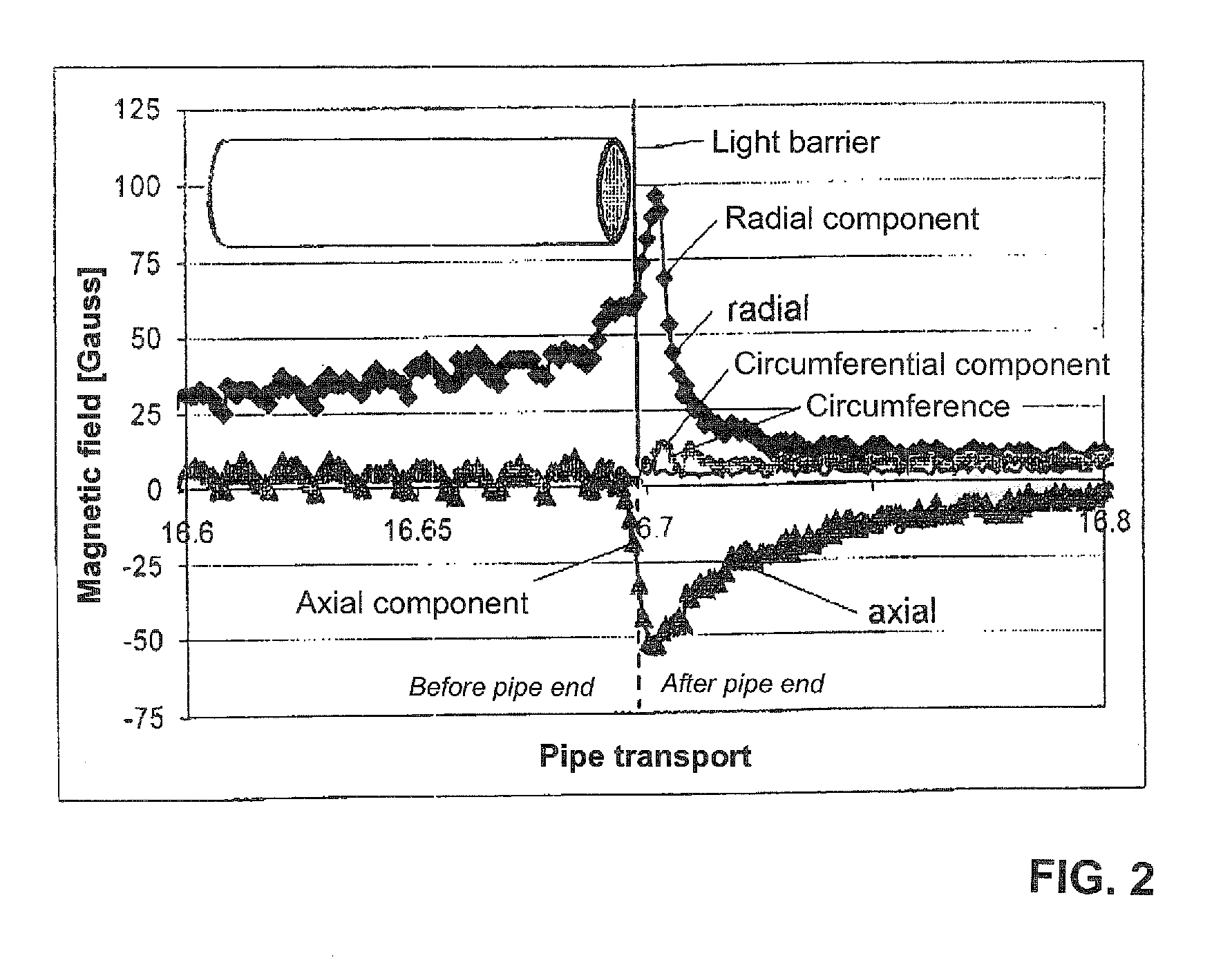
The invention relates to a method for the automated measurement of the residual magnetic field strength of magnetized ferromagnetic workpieces, especially steel tubes, the residual magnetic field exiting the face of the tube end being measured by means of a measuring probe. Instead of directly measuring the residual field strength on the face, the curve of at least one magnetic field component is measured on the outer surface of the tube at least in the region of the tube ends and beyond the tube ends and the residual field strength on the face is inferred on the basis of the previously determined correlations between the residual field strength measured on the face and on the tube surface.

Description

CROSS-REFERENCES TO RELATED APPLICATIONS[0001]This application is the U.S. National Stage of International Application No. PCT / DE2009 / 001657, filed Nov. 18, 2009, which designated the United States and has been published as International Publication No. WO 2010 / 060415 and which claims the priority of German Patent Application, Serial No. 10 2008 059 663.9, filed Nov. 27, 2008, pursuant to 35 U.S.C. 119(a)-(d).BACKGROUND OF THE INVENTION.[0002]The invention relates to a method for automated measurement of the residual magnetic field strength of magnetized ferromagnetic workpieces, in particular of pipes made of steel.[0003]Fault tests of steel pipes are frequently performed with magnetic methods or with magneto-inductive methods by using a magnetic bias. The test piece has then residual magnetic fields of a strength and direction that depends on the exact implementation of the test and the properties of the material. However, an undesired magnetization can also occur during pipe manu...

Claims


Application Information

Patent Timeline
Patent Type & Authority Patents(United States)
IPC IPC(8): G01N27/82G01N27/87G01R33/12
CPCG01R33/1215G01N27/87
Inventor KAACK, MICHAELNITSCHE, STEFANGERMES, ANDRE
Owner VALLOUREC DEUT
Learn More