Liquid resin molding system

a liquid resin and molding system technology, applied in the direction of mandrel separation arrangement, manufacturing tools, applications, etc., can solve the problems of heavy heating cylinder for plastication and measurement, inability to readily attach prior art injection units to movable plates,

Inactive Publication Date: 2015-01-27
NISSEI PLASTIC IND CO LTD
View PDF8 Cites 2 Cited by
  • Summary
  • Abstract
  • Description
  • Claims
  • Application Information

AI Technical Summary

Benefits of technology

[0010]An object of the present invention is to provide an injection molding system having a mold arranged to be closed by moving in a direction perpendicular to an axis of an injection unit such that no molten resin leaks from sprues.

Problems solved by technology

It is not readily possible to attach a prior art injection unit to the movable platen.
This is because a heating cylinder for plastication and measurement is heavy.

Method used


Image

  • Liquid resin molding system
  • Liquid resin molding system
  • Liquid resin molding system

Examples


Embodiment Construction

[0060]Like reference numerals indicate the same or corresponding elements throughout the drawings.

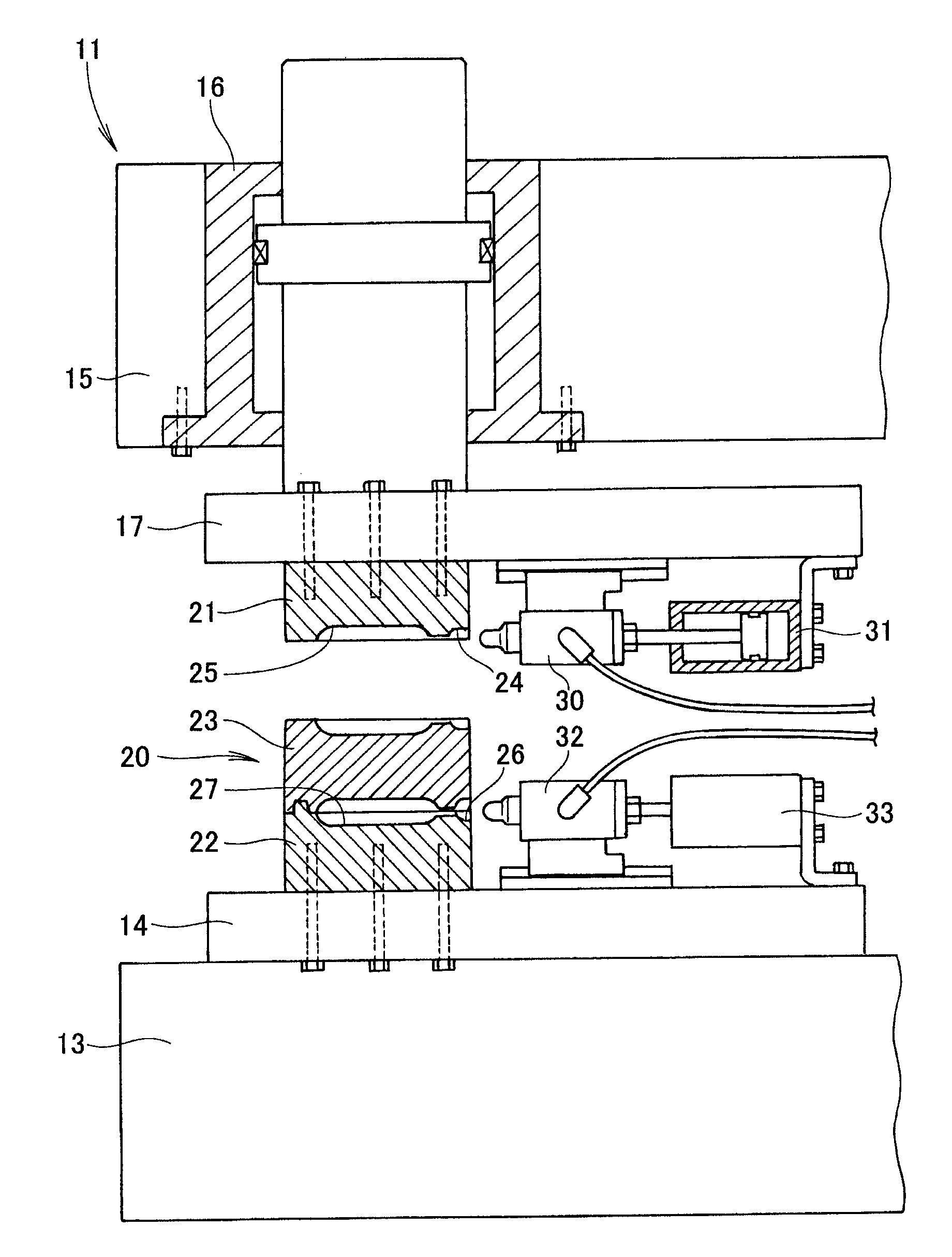
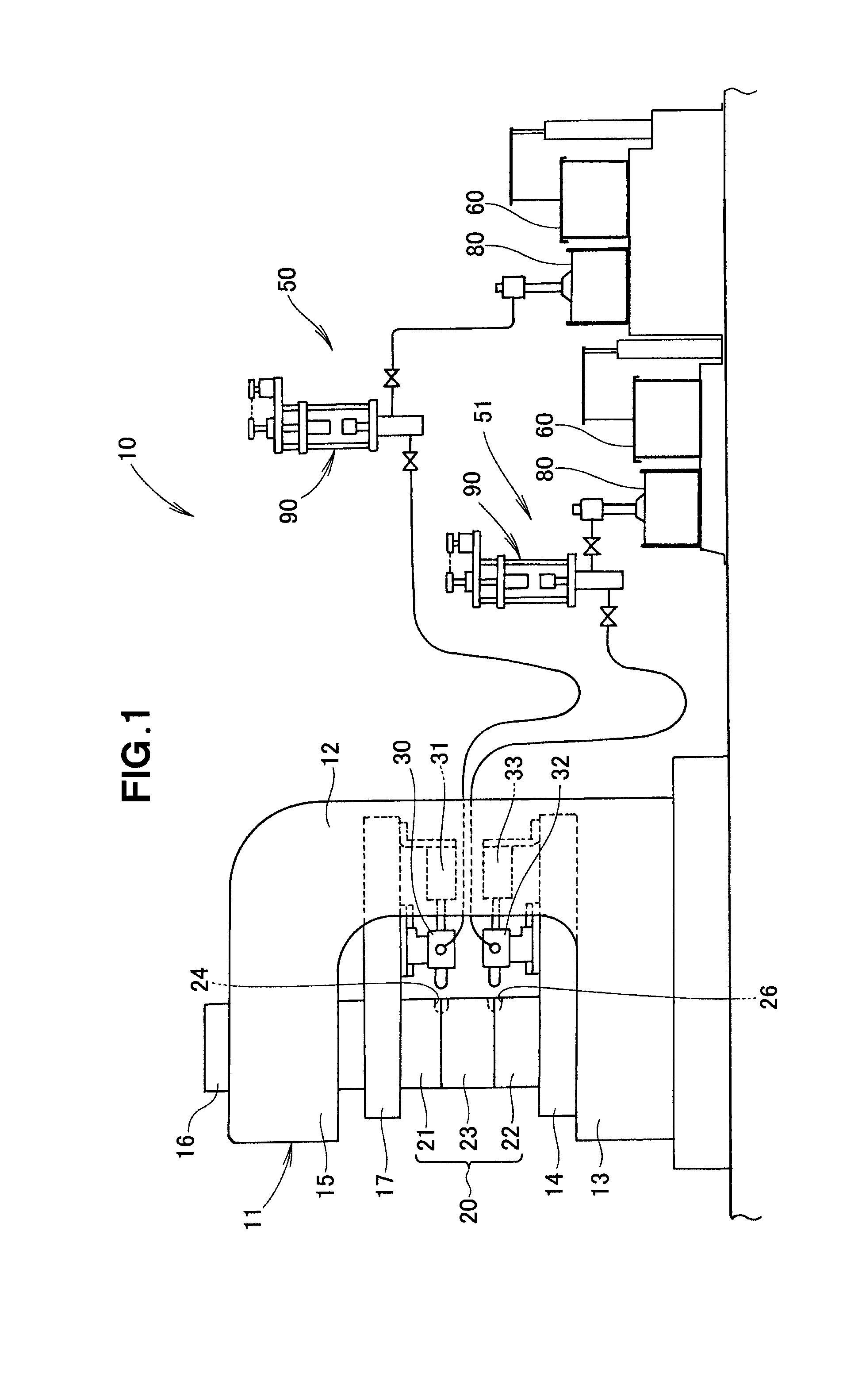
[0061]As shown in FIG. 1, a liquid resin molding system 10 includes a vertical mold clamping mechanism 11, a mold 20 to be closed by the vertical mold clamping mechanism 11, and first and second injection nozzles 30, 32 for injecting a liquid resin into the mold 20. The liquid resin molding system 10 also includes first and second nozzle touch mechanisms 31, 33 for pressing each of the first and second injection nozzles 30, 32 against the mold 20, a first liquid resin feeding apparatus 50 disposed separately from the first injection nozzle 30 and the first nozzle touch mechanism 31 for feeding a liquid resin to the first injection nozzle 30, and a second liquid resin feeding apparatus 51 disposed separately from the second injection nozzle 32 and the second nozzle touch mechanism 33 for feeding a liquid resin to the second injection nozzle 32.

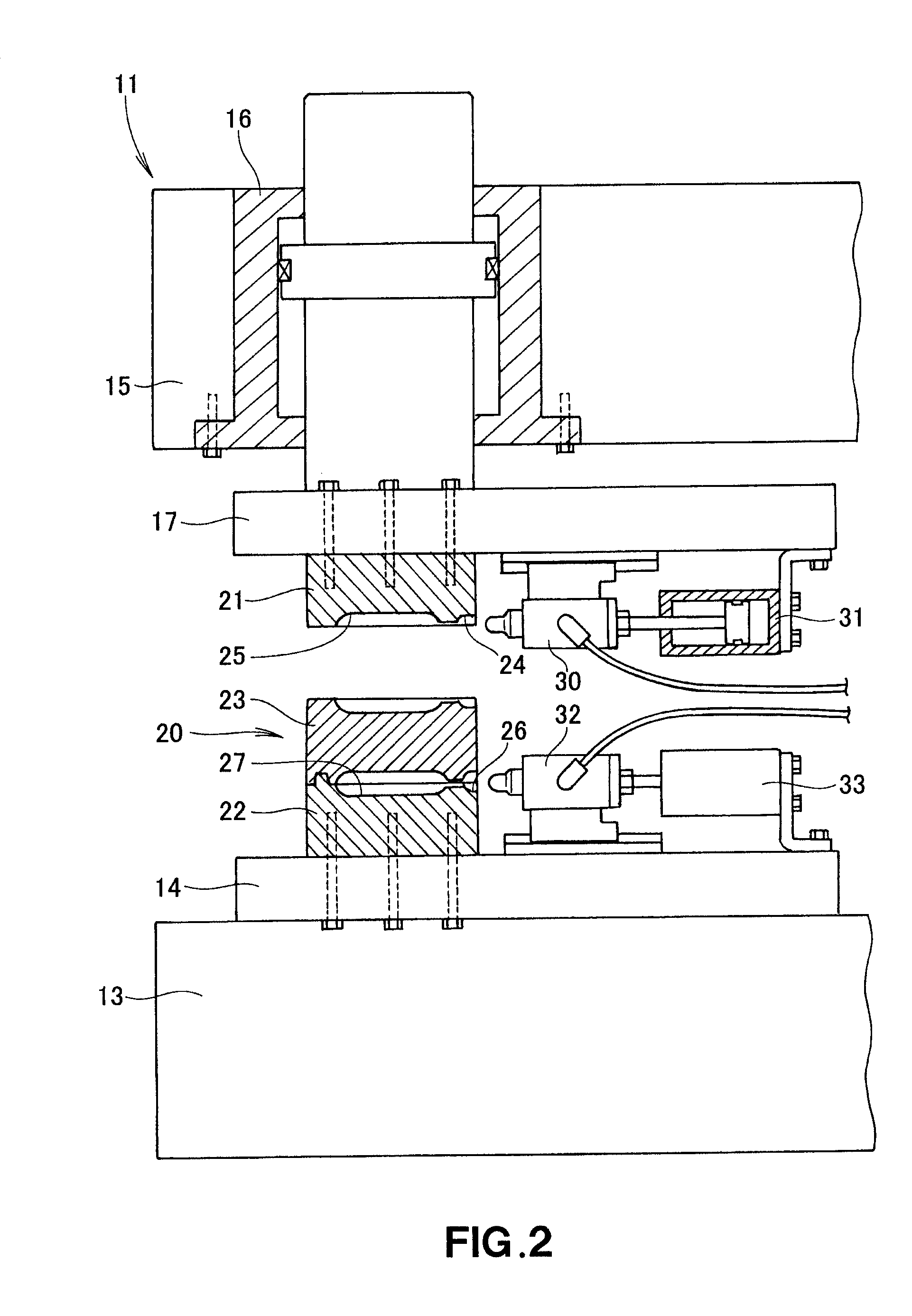
[0062]As shown in FIG. 2, the vertical mold ...


PUM

PropertyMeasurementUnit
temperatureaaaaaaaaaa
pressureaaaaaaaaaa
heightaaaaaaaaaa

Abstract

A liquid resin molding system has a stationary platen and a movable platen mounted for undergoing movement relative to the stationary platen. A mold has at least one cavity and includes a first mold member attached to the movable platen and a second mold member attached to the stationary platen. An injection nozzle is attached to the movable platen and is configured to receive a liquid resin and to inject the liquid resin into the mold cavity. A nozzle touch mechanism is attached to the movable platen for pressing the injection nozzle against the mold.

Description

FIELD OF THE INVENTION[0001]The present invention relates to an improvement in a liquid resin molding system.BACKGROUND OF THE INVENTION[0002]In many of injection molding apparatuses, a mold is closed by moving in the same direction as an axial direction of an injection unit. In contrast to such injection molding apparatuses, some injection molding apparatus has a mold arranged to be closed by moving in a direction perpendicular to an axis of an injection unit, as disclosed in JP-U-46-26300.[0003]FIGS. 15A and 15B hereof schematically show a well-known injection molding apparatus 200 disclosed in JP-U-46-26300. As shown in FIG. 15A, the injection molding apparatus 200 includes a base 201, an injection unit 202 disposed horizontally on the base 201, and a mold clamping mechanism 203 vertically movably disposed on the base 201.[0004]In the mold clamping mechanism 203, a mold assembly 207 is shown in a closed position where a first cavity 208 is formed between an upper mold 204 and an ...

Claims


Application Information

Patent Timeline
Patent Type & Authority Patents(United States)
IPC IPC(8): B21C45/00B29C45/04B29C45/07B29C45/17B29C45/23B29C45/32B29C45/42B29C67/24B29K83/00
CPCB29C45/076B29C45/231B29C45/32B29C45/322B29C45/0416B29C67/246B29K2083/005B29C45/1761B29C45/42
Inventor IKEDA, TORU
Owner NISSEI PLASTIC IND CO LTD
Why Eureka
Try Eureka