
Steering device

a steering device and steering column technology, applied in the direction of steering column, steering parts, vehicle components, etc., can solve the problems of difficult to reduce the cost, limited retaining force that can be increased, complex manufacturing process, etc., to achieve cost reduction, increase the force of retaining the tilt position in the locked state, and maintain the tilt position. the effect of stability

Inactive Publication Date: 2015-01-13
YAMADA MANUFACTURING CO LTD
View PDF17 Cites 6 Cited by
  • Summary
  • Abstract
  • Description
  • Claims
  • Application Information

AI Technical Summary

Benefits of technology

The solution effectively increases the force of retaining the tilt position while allowing smooth adjustments by using a simple structure that maintains the locked state with enhanced frictional force, reducing manufacturing complexity and costs, and preventing deviation of the steering column.

Problems solved by technology

Thus, a manufacturing process is complex, and it is difficult to reduce the cost.
In Japanese Unexamined Patent Application Publication No. 2006-298072, although the force of retaining a tilt position is increased by increasing the diameter of the friction washer, since the range where the diameter can be increased is limited by a layout or the like, the retaining force that can be increased is also limited.

Method used


Image

  • Steering device
  • Steering device
  • Steering device

Examples


first embodiment

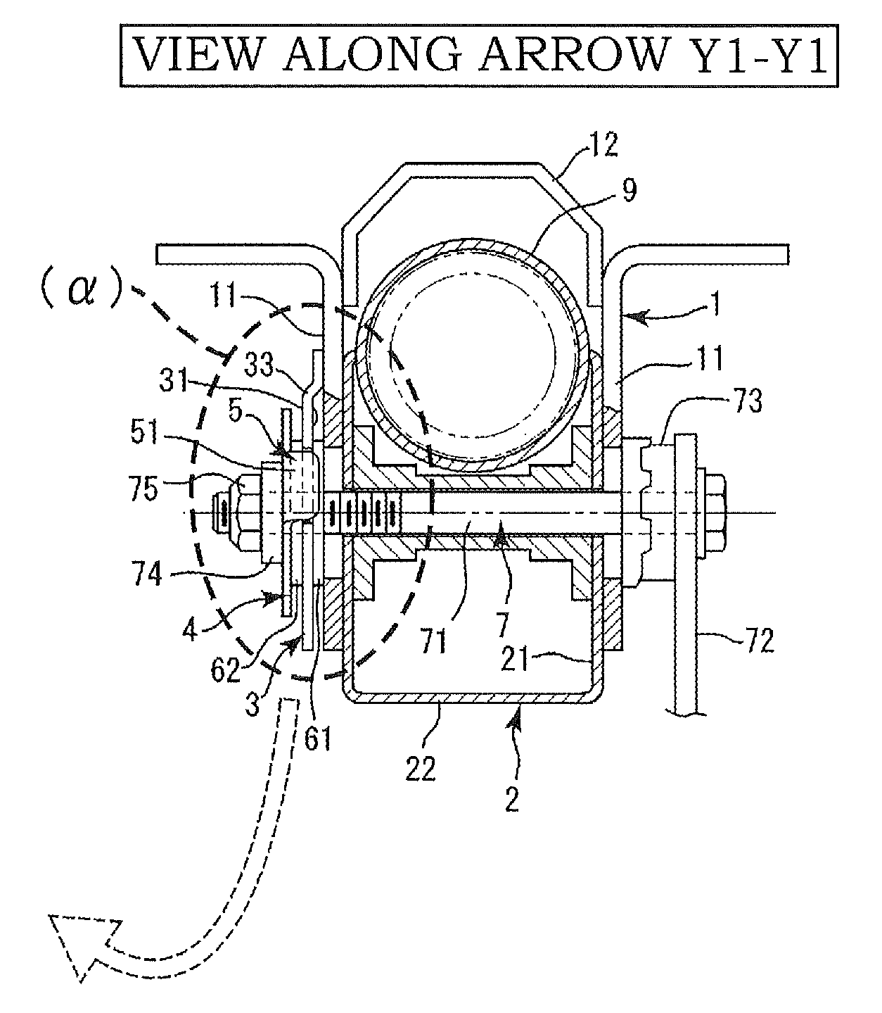
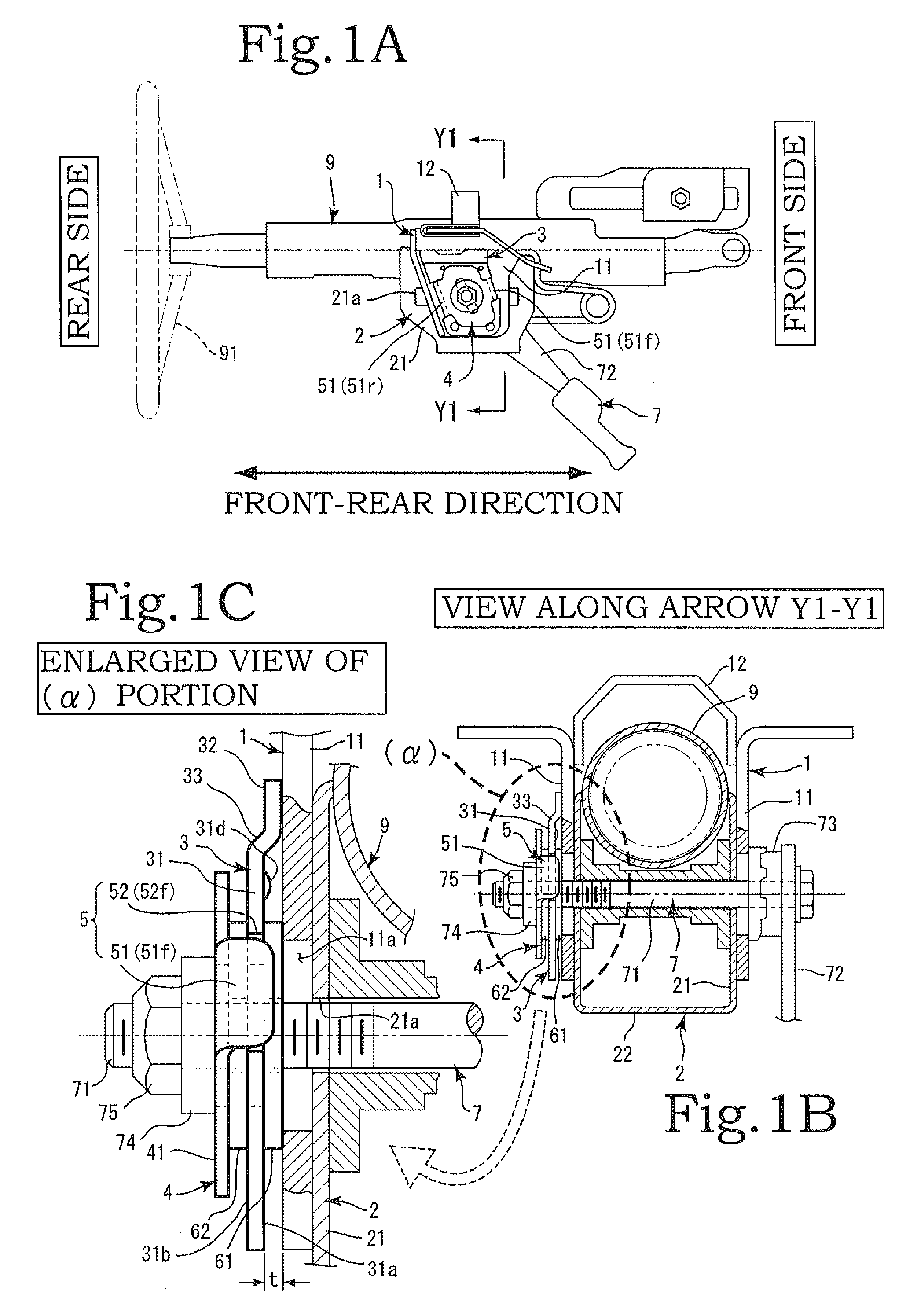
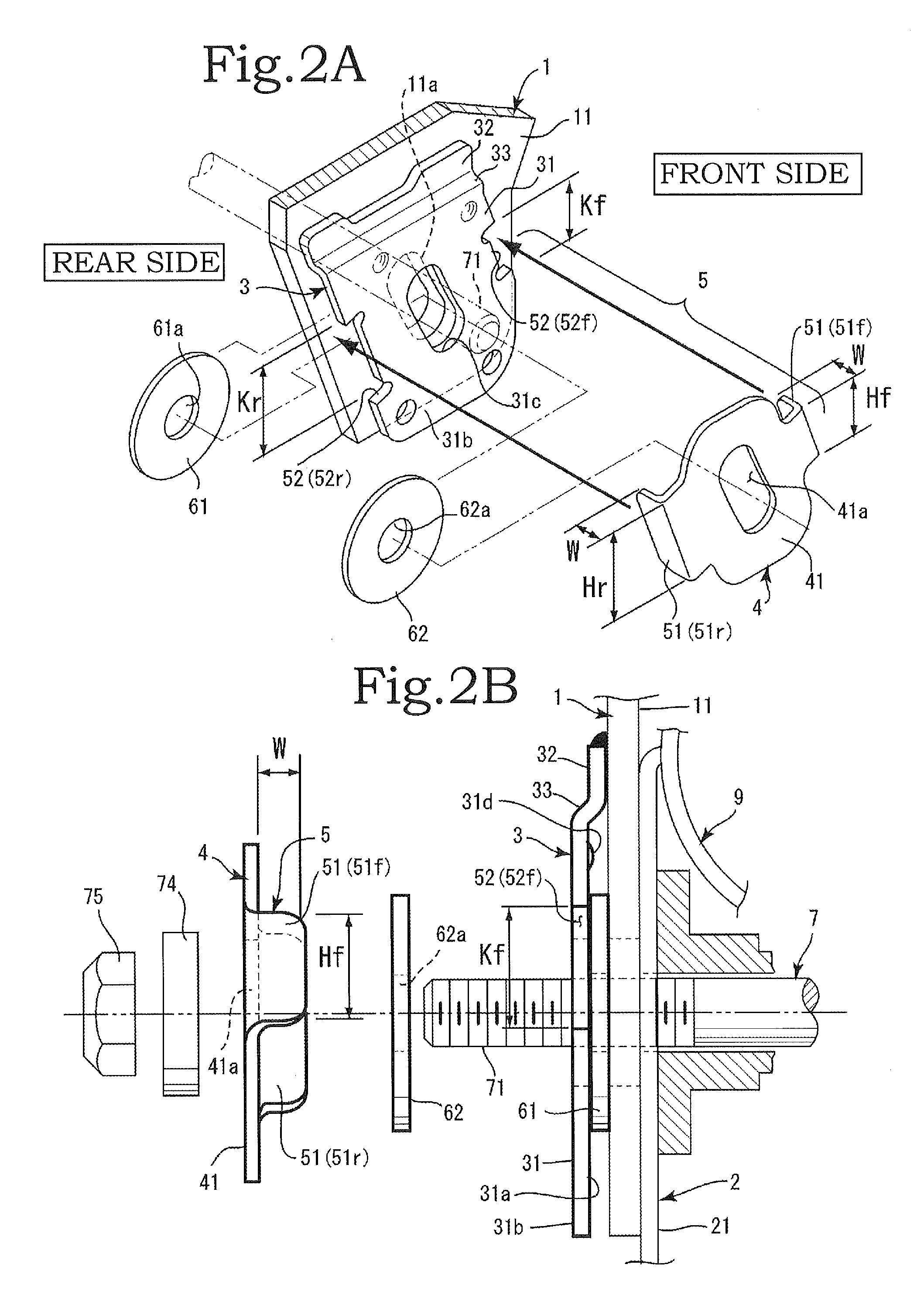
[0050]The engagement means 5 includes an engaging portion 51 and an engaged portion 52. One of the engaging portion 51 and the engaged portion 52 is formed on the pressing plate 4, and the other is formed on the friction plate 3. Specifically, the engaging portion 51 is formed in a projection shape, and the engaged portion 52 is formed in a notch shape. In the present invention, the engaging portion 51 is formed on the pressing plate 4, and the engaged portion 52 is formed on the friction plate 3 (see FIG. 1 and FIG. 2).

[0051]The engaging portions 51 are formed at both ends in the front-rear direction of the planar portion 41 of the pressing plate 4. Both engaging portions 51 are formed in an approximately rectangular shape such as an oblong shape or a square shape, and actually, are formed from a metal plate to be integrated with the pressing plate 4 by press working or the like. The engaging portion 51 is a piece of a board that is bent to make a right angle (or make an approximat...

second embodiment

[0055]As in the present invention shown in FIG. 5, the engaging portions 51 may be formed on both sides in the front-rear direction of the friction plate 3, and the engaged portions 52 may be formed on both sides in the front-rear direction of the pressing plate 4. Specifically, the engaging portions 51 are formed at both ends in the front-rear direction of the planar portion 31 of the friction plate 3 so as to extend at the right angle toward the outer side from the outer surface 31b. Moreover, the engaged portions 52 having a notch shape are formed on both sides in the front-rear direction of the pressing plate 4.

[0056]In the second embodiment, the projection-shaped engaging portion 51 formed on the friction plate 3 is engaged with the notch-shaped engaged portion 52 formed in the pressing plate 4. In this case, the projection-shaped engaging portion 51 formed on the friction plate 3 is formed so as to protrude toward the engaged portion 52 of the pressing plate 4.

[0057]Thus, the ...


PUM


Abstract

A steering device includes a fixed bracket, a movable bracket, a friction plate, a first friction washer, a pressing plate, engagement units, a second friction washer, and a fastening tool. The friction plate is attached to face, with an appropriate gap, at least one of both fixed side portions of the fixed bracket. The first washer is inserted between the fixed side portion and the friction plate. The pressing plate is attached to an outer surface of the friction plate. The engagement unit causes the pressing plate to be detachably attached and be immovable at least in a vertical direction. The second friction washer is clamped between the pressing plate and the friction plate. The fixed bracket, the friction plate, the first friction washer, the second friction washer, and the pressing plate are connected by penetrating therethrough a lock bolt of the fastening tool.

Description

BACKGROUND OF THE INVENTION[0001]1. Field of the Invention[0002]The present invention relates to a steering device which in particular is, when implementing tilt and telescopic adjustment, capable of strengthening a locked state thereof and allowing a tilt and telescopic adjustment operation in an unlocked state to be performed smoothly.[0003]2. Description of the Related Art[0004]In the related art, in order to increase the force of retaining the position of a steering wheel to the position after tilt adjustment, a structure in which a pressure-contact frictional force caused by an axial force of a lock bolt is increased by superimposing a plurality of friction members is employed. Structures of this type are disclosed in Japanese Examined Utility Model Application Publication No. S62-19483 and Japanese Unexamined Patent Application Publication No. 2006-298072. Japanese Examined Utility Model Application Publication No. S62-19483 and Japanese Unexamined Patent Application Publicati...

Claims


Application Information

Patent Timeline
Patent Type & Authority Patents(United States)
IPC IPC(8): B62D1/18B62D1/184
CPCB62D1/184
Inventor HIROOKA, KOUJISUGISHITA, SUGURU
Owner YAMADA MANUFACTURING CO LTD
Learn More