
System, operation cell, method, product manufacturing method, and marker for locating operation position

a technology of operation cell and operation position, applied in the field of system, operation cell, method, product manufacturing method, and marker for locating operation position, can solve the problems of screwing operation erroneous operation, erroneous operation frequently occurring from screwing operation, and not possible only by comparing numbers, so as to reduce the frequency of occurrence of defective products caused by forgetting an operation, test process steps, and manufacturing process

Inactive Publication Date: 2014-06-24
FUJITSU LTD
View PDF36 Cites 3 Cited by
  • Summary
  • Abstract
  • Description
  • Claims
  • Application Information

AI Technical Summary

Benefits of technology

The operation position locating system uses image processing to detect the position of an operation, allowing for automatic identification of incomplete operations. This reduces the number of steps required for instruction and testing, reduces the likelihood of defective products, and increases manufacturing yield.

Problems solved by technology

In a manufacturing process of a product requiring a number of operations to be performed by workers, there often occur erroneous operations by a worker forgetting an operation or failing to complete an operation.
In the assembly process, erroneous operations frequently occur from screwing operations.
However, it is not possible only by comparing the numbers to concretely determine which operation has been forgotten.
At present, there are still a number of erroneous operations even using these operation tools.
As a result, there frequently occurs defective manufacture, which requires inspection and repair within a manufacturing process.
Thus, in a manufacturing process to be performed by a number of operations by workers, forgetting operations is a serious problem.
However, there are the following two problems with the system described in the patent document 2.
The first problem is that it is necessary to attach a transmitter of ultrasonic signal or radio signal to a tool.
Such necessity cause a problem because the transmitter requires more power, the wiring for supply of power to the transmitter can be the obstacle to an operation, and / or the transmitter can not be attached to some types of existing tools.
The second problem is an assumption that it is predetermined that the positional relation between a workpiece and receivers is statically determined.
In some process steps, the position and the direction of a product are uncertain until a practical operation is performed due to various reasons including the convenience of a worker, etc.

Method used


Image

  • System, operation cell, method, product manufacturing method, and marker for locating operation position
  • System, operation cell, method, product manufacturing method, and marker for locating operation position
  • System, operation cell, method, product manufacturing method, and marker for locating operation position

Examples


Embodiment Construction

[0042]The modes for embodying the present invention are described below in detail with reference to the attached drawings. Embodiments applied to the screwing operation in assembling a printed circuit board unit is mainly described below, but it is obvious that the embodiments of the present invention are not limited with respect to the type of product or operation to which the embodiments of the present invention is applied.

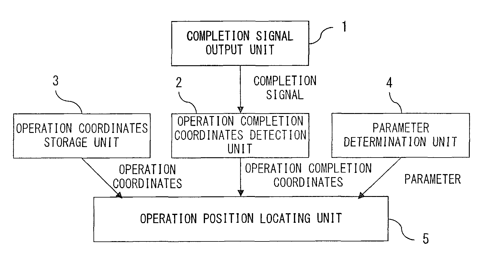
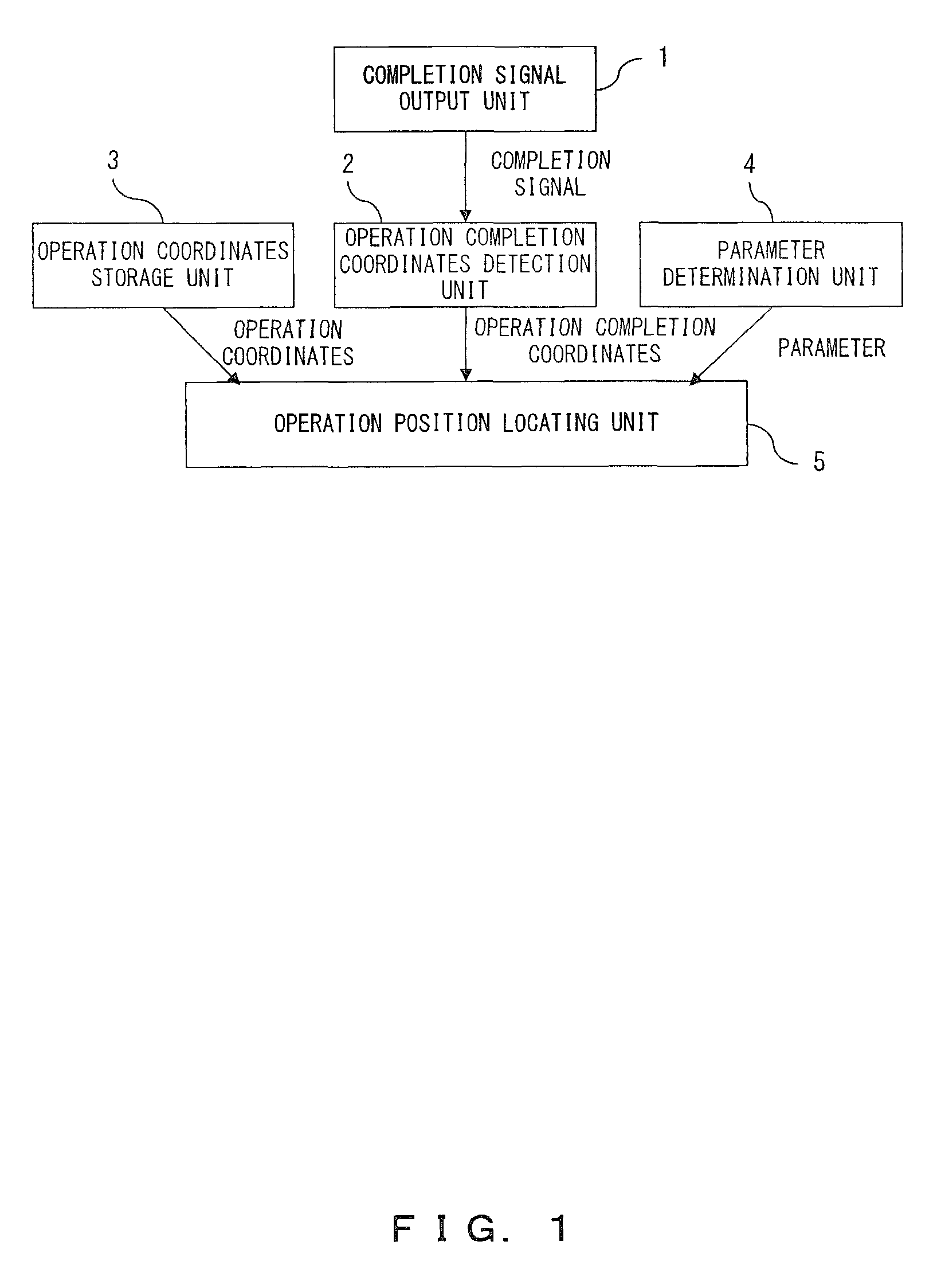
[0043]FIG. 1 is a block diagram of the function according to a mode for embodying the present invention of the operation position locating system. In the present embodiment, in the manufacturing process of a product including one or more operations to be performed using a tool, an operation practically performed is distinguished in the operations to be performed by locating the position on the product where the operation has been performed.

[0044]When one operation is completed, a completion signal output unit 1 outputs a completion signal, and an operation compl...


PUM

PropertyMeasurementUnit
lengthaaaaaaaaaa
lengthaaaaaaaaaa
distanceaaaaaaaaaa

Abstract

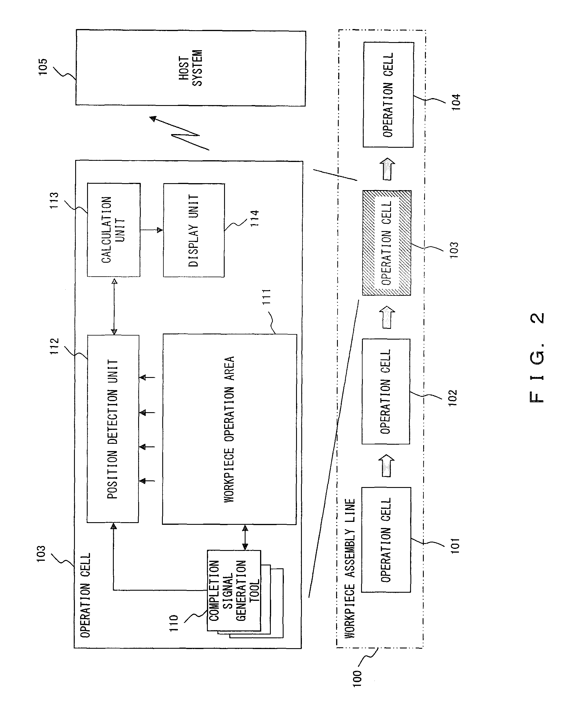
An operation position locating system locates a position on a product where an operation is performed in a manufacturing process of the product including one or more operations to be performed. The system includes an operation completion coordinates detection unit and an operation position locating unit. The operation completion coordinates detection unit processes a plurality of images obtained by capturing from a plurality of viewpoints a range including an operation completion position where an operation is completed when the operation is completed, thereby detecting a set of operation completion coordinates representing the operation completion position. The operation position locating unit obtains a set of operation coordinates representing an operation position where the operation is to be performed on each operation, and locates the operation position corresponding to the operation completion position based on the set of operation completion coordinates and the one or more obtained sets of operation coordinates.

Description

BACKGROUND OF THE INVENTION[0001]1. Field of the Invention[0002]The present invention relates to the technology of locating the position of an operation performed in a manufacturing process of a product.[0003]2. Description of the Related Art[0004]In a manufacturing process of a product requiring a number of operations to be performed by workers, there often occur erroneous operations by a worker forgetting an operation or failing to complete an operation. For example, the manufacturing process of a large electronic equipment unit, a printed circuit board unit, a communication equipment unit, etc. includes an assembly process of parts, and the assembly process includes a number of screwing operations for attaching a part to another part. In the assembly process, erroneous operations frequently occur from screwing operations.[0005]Examples of erroneous operations are stopping a screwing operation before reaching a specified torque of a screw, forgetting to complete a screwing operati...

Claims


Application Information

Patent Timeline
Patent Type & Authority Patents(United States)
IPC IPC(8): G06F19/00B23Q17/00G01N21/00G05B19/00G05B19/418G06Q50/00G06Q50/04
CPCG05B19/41805G05B19/41875G05B2219/31027G05B2219/37567Y10T29/49764Y10T29/49769Y02P90/02
Inventor KASUGA, TOSHINORIYAMANISHI, HIROKAZU
Owner FUJITSU LTD
Learn More