Liquid crystal display device
a liquid crystal display and display device technology, applied in non-linear optics, instruments, optics, etc., can solve the problems of significantly deteriorating transmittance and deteriorating image quality, and achieve high transmittance, prevent generation, and high definition
- Summary
- Abstract
- Description
- Claims
- Application Information
AI Technical Summary
Benefits of technology
Problems solved by technology
Method used
Image
Examples
first embodiment
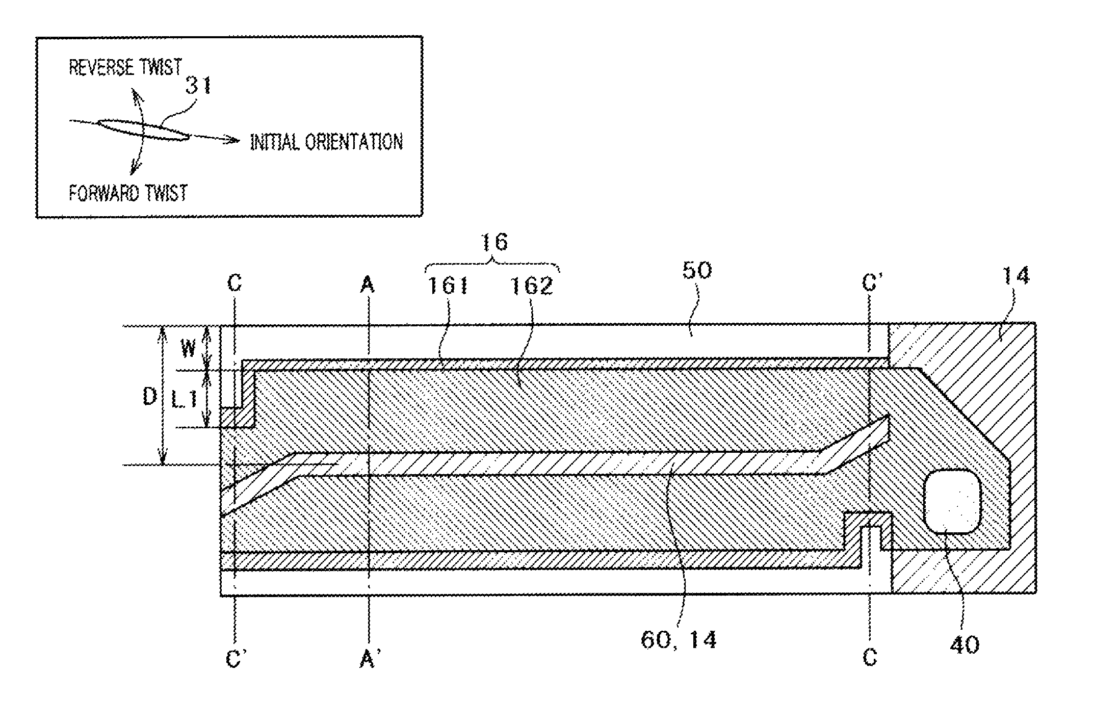
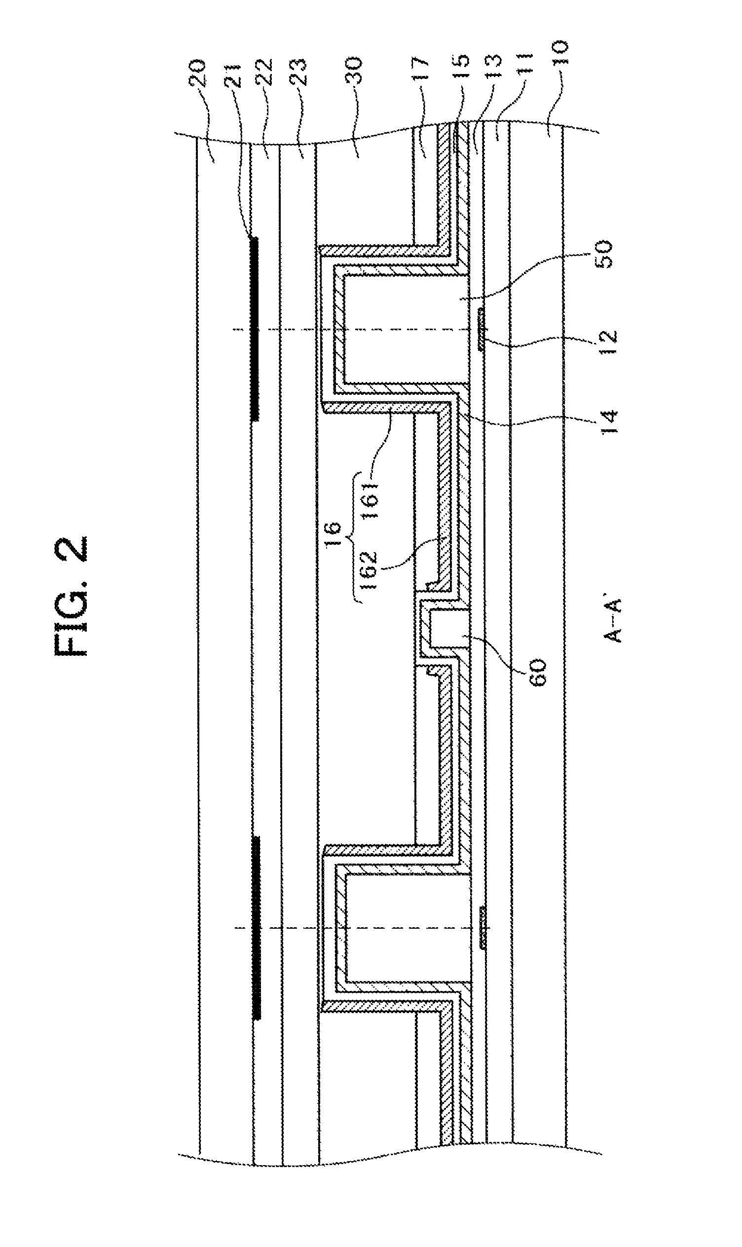
[0035]FIG. 1 shows a structure of a pixel according to the present invention as a plan view. FIG. 2 is a cross-section taken on line A-A′ of FIG. 1. FIG. 3 is a cross section taken on line B-B′ of FIG. 1. As FIG. 1 shows, the pixel according to the present invention has different cross section structures between the area around the center of the pixel (taken on line A-A′) and the area around the end part of the pixel (taken on line B-B′).
[0036]Referring to FIG. 1, a small wall 60 transversely extends along the center of the pixel. Large walls 50 transversely extend at the boundary of the pixel while interposing the small wall 60. A common electrode 14 is formed on the upper surface of the small wall 60. A wall electrode 161 is formed at the inner side of the large wall 50, and a plane electrode 162 is formed between the small wall 60 and the large wall 50. A pixel electrode 16 is formed of the wall electrode 161 and the plane electrode 162. A through hole 40 for connecting a video s...
second embodiment
[0054]FIG. 7 is a plan view of the pixel according to a second embodiment of the present invention. FIG. 8 is a cross section taken on line C-C′ of FIG. 7. The cross section taken on line A-A′ of FIG. 7 is the same as the one used for explanation referring to FIG. 2. Referring to FIG. 7, like the first embodiment, the width of the large wall 50 is increased at the end part of the pixel, and the wall electrode 161 is bent toward the center of the pixel. The characteristic of the embodiment is that the small wall 60 is bent in the direction where the wall electrode 161 is bent in association with increase in the width of the large wall 50 as shown in FIG. 7. In other words, the small wall 60 is bent at the area around where the pixel electrode 161 is bent in the direction away from the bent pixel electrode 161.
[0055]FIG. 8 is a cross section taken on line C-C′ of FIG. 7 representing a structure of the end part of the pixel. As FIG. 8 shows, one of the large walls 50 has the larger wid...
third embodiment
[0061]FIG. 12 is a plan view of a pixel according to a third embodiment of the present invention. The structure shown in FIG. 12 is configured by extending the bent structure of the common electrode 14 formed on the small, wall 60 as shown in FIG. 7 according to the second embodiment to the area around the through hole 40 at the end part of the pixel. Extending the common electrode 14 formed on the small wall 60 to the area around the through hole 40 allows the liquid crystal around the through hole 40 to serve as the display region, thus improving the transmittance.
[0062]As FIG. 12 shows, the structure has the bent small wall 60, which allows the liquid crystal molecule 31 to be twisted forward in the liquid crystal layer around the through hole 40, suppressing generation of the domain. That is, the transmission region may be widened while suppressing generation of the domain, resulting in improved transmittance. A region A enclosed by the dashed line as shown in FIG. 12 serves as ...
PUM
| Property | Measurement | Unit |
|---|---|---|
| height | aaaaa | aaaaa |
| relative transmittance | aaaaa | aaaaa |
| relative transmittance | aaaaa | aaaaa |
Abstract
Description
Claims
Application Information
 - R&D
- Intellectual Property
- Life Sciences
- Materials
- Tech Scout
- Unparalleled Data Quality
- Higher Quality Content
- 60% Fewer Hallucinations
Browse by: Latest US Patents, China's latest patents, Technical Efficacy Thesaurus, Application Domain, Technology Topic, Popular Technical Reports.
© 2025 PatSnap. All rights reserved.Legal|Privacy policy|Modern Slavery Act Transparency Statement|Sitemap|About US| Contact US: help@patsnap.com


