
Apparatuses and methods for harvesting energy from prosthetic limbs

a technology for prosthetic limbs and apparatuses, applied in the direction of prosthesis, electric generator control, machines/engines, etc., can solve the problems of limiting the amount of mechanical movement available to move an electromechanical generator as a means, limiting the amount of battery power to the user, and limiting the amount of mechanical force on some components in such a devi

Active Publication Date: 2015-01-06
KCF TECHNOLOGIES
View PDF23 Cites 28 Cited by
  • Summary
  • Abstract
  • Description
  • Claims
  • Application Information

AI Technical Summary

Benefits of technology

The patent describes an apparatus and method for harvesting energy from the motion of a prosthetic limb. This involves using a hydraulic amplifier and generator to convert the mechanical energy of the limb's movement into electrical energy, which can then be used to power electrical loads or stored in a reservoir. The technical effect is the ability to recycle energy from a prosthetic limb, reducing the need for batteries and other external energy sources.

Problems solved by technology

Even if the device does not provide powered motion such as actively propelling the user forward, they may still use energy when in motion to run the valves or other actuators that control the motion of the joint(s).
This battery is limiting to the user because it must be recharged periodically.
One issue encountered when designing energy harvesting devices for prosthetics is that only a small amount of deflection is tolerable in a prosthetic limb, therefore limiting the amount of mechanical movement available to move an electromechanical generator as a means of gathering energy.
The generator could be directly coupled to the deflecting components, for instance through a series of gears, but the amount of force on some of the components in such a device is often too large for the small electromechanical generator components that can be used in prosthetics, and these high forces can be a significant noise source.
What is currently lacking in the art is an energy harvesting device capable of amplifying the small amount of deflection available when a prosthetic limb is in use to generate a larger mechanical motion that can be used to drive an electromechanical generator while reducing the force exerted on the electromechanical generator.

Method used


Image

  • Apparatuses and methods for harvesting energy from prosthetic limbs
  • Apparatuses and methods for harvesting energy from prosthetic limbs
  • Apparatuses and methods for harvesting energy from prosthetic limbs

Examples


Embodiment Construction

[0016]Reference will now be made in detail to specific embodiments or features, examples of which are illustrated in the accompanying drawings. Generally, corresponding or similar reference numbers will be used, when possible, throughout the drawings to refer to the same or corresponding parts.

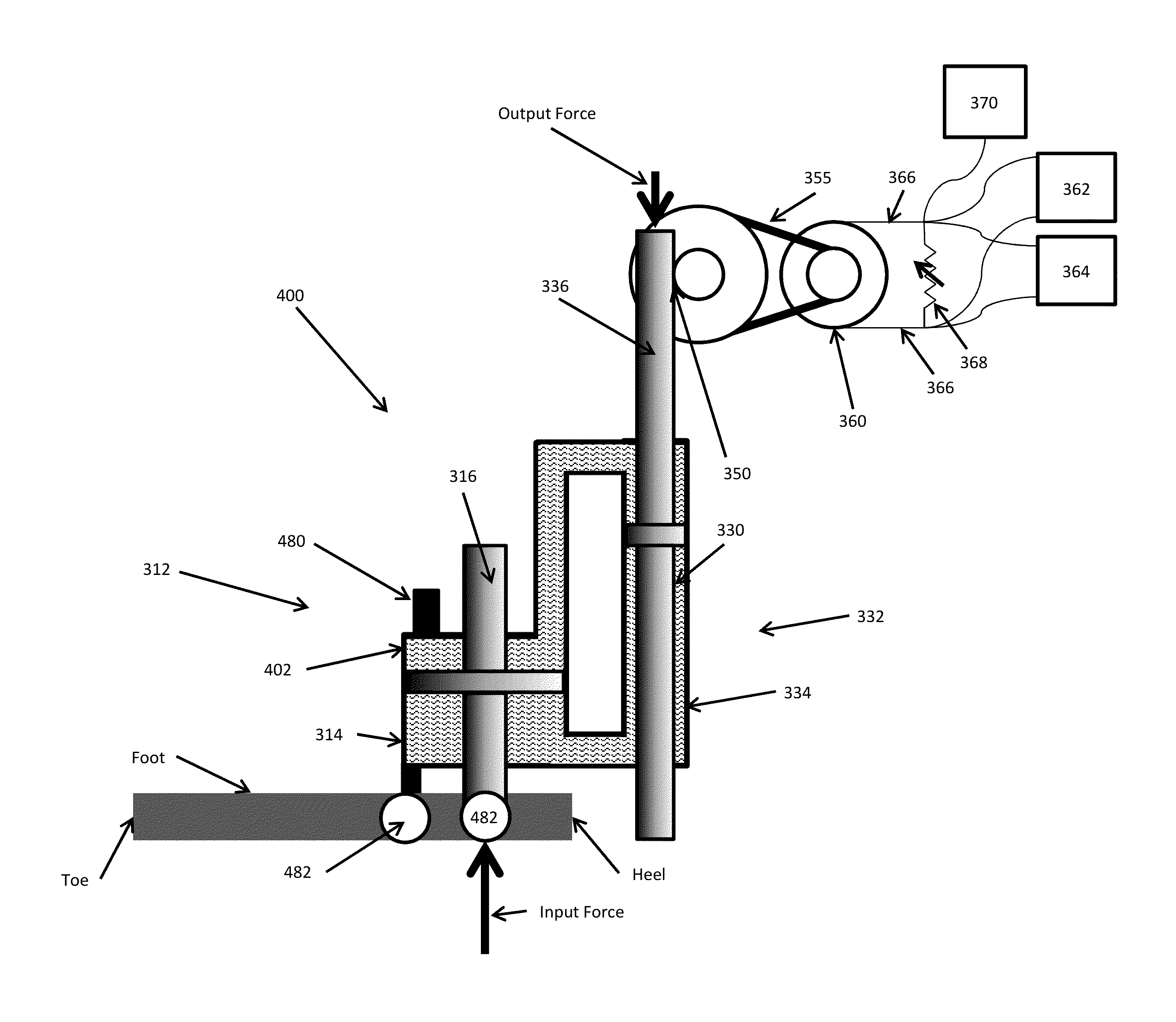
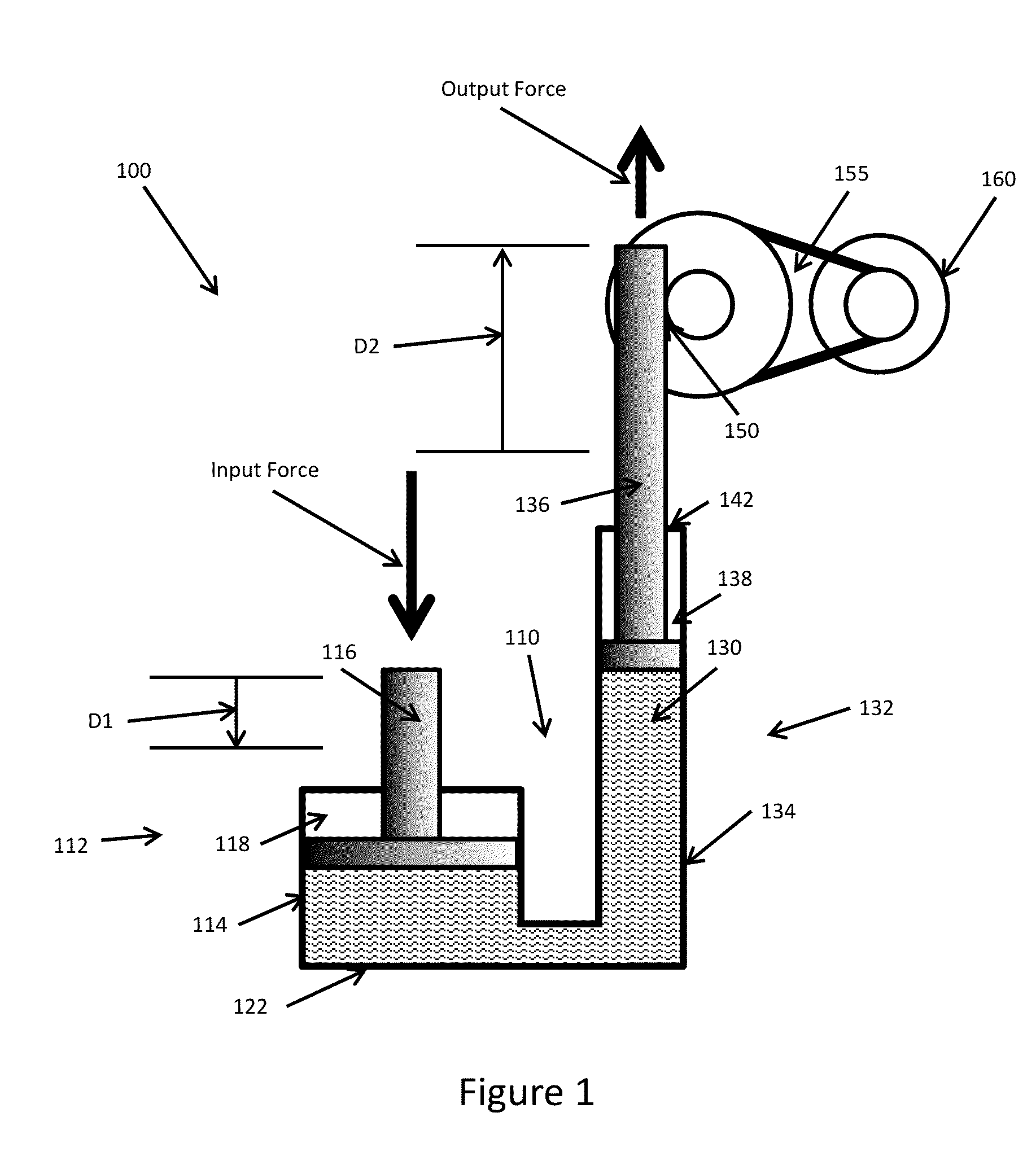
[0017]Referring now to FIG. 1, an exemplary embodiment of an apparatus 100 for harvesting energy from motion of a prosthetic limb is illustrated. As would be appreciated by persons skilled in the art, the prosthetic limb has motion in at least one degree of freedom. In the embodiment illustrated, the apparatus 100 includes a hydraulic amplifier 110 and a mechanical arrangement 150 configured to couple output motion and associated output force of the hydraulic amplifier 110 to a generator 160.

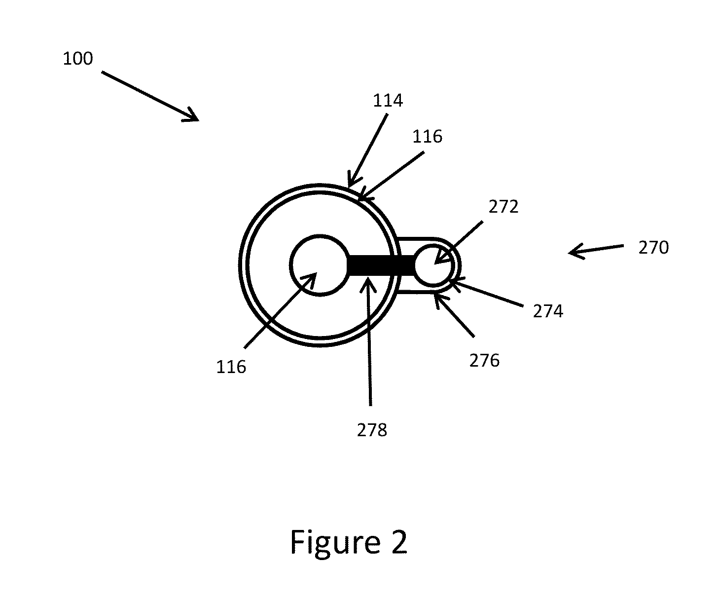
[0018]According to various aspects, the hydraulic amplifier 110 includes an input member 112 and an output member 132. The input member 112 may include a first hydraulic cylinder 114 and a first piston 116...


PUM


Abstract

An apparatus for harvesting energy from motion of a prosthetic limb, wherein the prosthetic limb has motion in at least one degree of freedom, may include a hydraulic amplifier mechanically coupled with a generator. The hydraulic amplifier may include an input member configured to receive an input motion when a first motion in a degree of freedom of the prosthetic limb causes pressure and motion of hydraulic fluid. The hydraulic amplifier is configured to amplify the input motion of the input member to a greater output motion. The generator is configured to convert mechanical energy of the output motion into corresponding electrical energy delivered to one of an electrical load and an electrical storage reservoir.

Description

GOVERNMENT LICENSE RIGHTS[0001]This invention was made with government support under Contract No. W81XWH-10-C-0192 awarded by the U.S. Army TATRC (U.S. Army Medical Research Acquisition Activity, 820 Chandler St., Fort Detrick, MD 21702-5014). The government has certain right in the invention.CROSS-REFERENCE TO RELATED APPLICATIONS[0002]The present disclosure is related to copending U.S. patent application Ser. No. 13 / 481,770, now U.S. Pat. No. 8,698,329, the disclosure of which is incorporated herein by reference.TECHNICAL FIELD[0003]The present disclosure relates generally to apparatuses and methods for harvesting energy from prosthetic limbs and, more particularly, to hydraulic energy harvesting devices for prosthetic limbs.BACKGROUND[0004]The field of prosthetic devices has advanced greatly through the years. Many current lower-limb prosthetics use sensors, microprocessor controllers, and valves or other actuators to assist the user's gait motion. The devices range from prosthet...

Claims


Application Information

Patent Timeline
Patent Type & Authority Patents(United States)
IPC IPC(8): F02B63/04F03G7/08H02K7/18A61F2/50A61F2/68A61F2/70A61F2/74F03G5/06
CPCA61F2/68F03G5/06H02K7/1853A61F2002/5006A61F2002/708A61F2002/745A61F2/70A61F2/74
Inventor LOVERICH, JACOB J.KRAIGE, DAVID R.FRANK, JEREMY E.GEIGER, RICHARD T.
Owner KCF TECHNOLOGIES
Learn More