
Liquid ejection apparatus, controller therefor, nonvolatile storage medium storing program for controlling the apparatus

a technology of liquid ejection and controller, which is applied in the direction of printing, other printing apparatus, etc., can solve the problems of deteriorating image quality, increasing waste liquid, and increasing so as to prevent the increase in increase the amount of waste liquid, and improve the viscosity of the liquid in the head

Active Publication Date: 2015-01-06
BROTHER KOGYO KK
View PDF25 Cites 1 Cited by
  • Summary
  • Abstract
  • Description
  • Claims
  • Application Information

AI Technical Summary

Benefits of technology

The patent text discusses the issue of waste liquid and viscosity control during liquid ejection. When liquid is frequently ejected, it creates more waste liquid. To prevent this, humidification can be used, but it takes longer for the liquid to become less viscous. As a result, the speed and size of liquid droplets ejected from the ejection opening may be affected, leading to a lower density of liquid and impaired image quality. The patent aims to solve this problem by proposing a method to control viscosity to improve liquid ejection.

Problems solved by technology

However, frequent preliminary ejections lead to an increase in an amount of waste liquid.
Thus, a relatively long time may be required for lowering a viscosity of part of the liquid located on an upstream side of the ejection opening in the liquid-flow direction, and the viscosity of the liquid in the ejection opening may become too low.
If the viscosity of the liquid in the ejection opening is excessively low, each of a size (volume) and a speed of a liquid droplet ejected from the ejection opening may deviate from a predetermined value, and a density of the liquid may become too low, which may deteriorate an image quality.

Method used


Image

  • Liquid ejection apparatus, controller therefor, nonvolatile storage medium storing program for controlling the apparatus
  • Liquid ejection apparatus, controller therefor, nonvolatile storage medium storing program for controlling the apparatus
  • Liquid ejection apparatus, controller therefor, nonvolatile storage medium storing program for controlling the apparatus

Examples


Embodiment Construction

[0022]Hereinafter, there will be described an embodiment of the present invention by reference to the drawings.

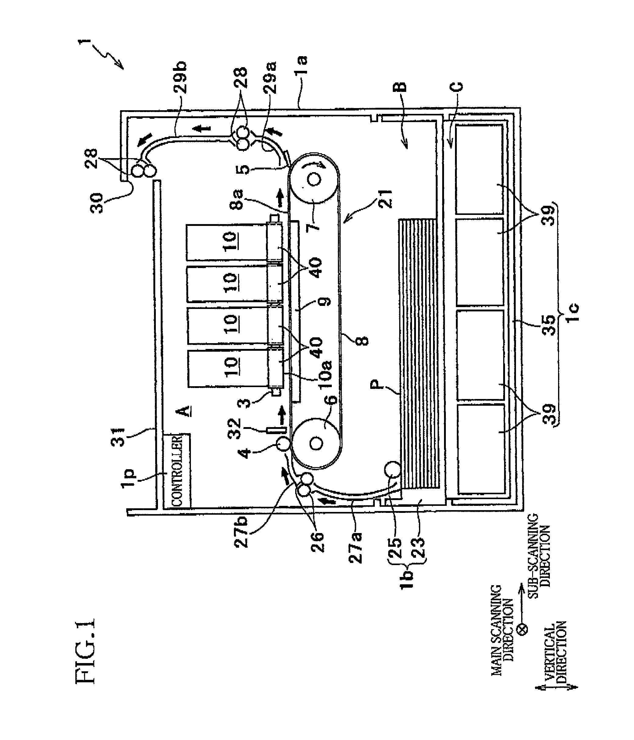
[0023]First, there will be explained an overall construction of an ink-jet printer 1 as an embodiment of a liquid ejection apparatus to which the present invention is applied.

[0024]The printer 1 includes a casing 1a having a rectangular parallelepiped shape. A sheet-discharge portion 31 is provided on a top plate of the casing 1a. An inner space of the casing 1a is divided into spaces A, B, and C in order from an upper side thereof. In the spaces A and B is formed a sheet conveyance path extending from a sheet-supply unit 1b to the sheet-discharge portion 31.

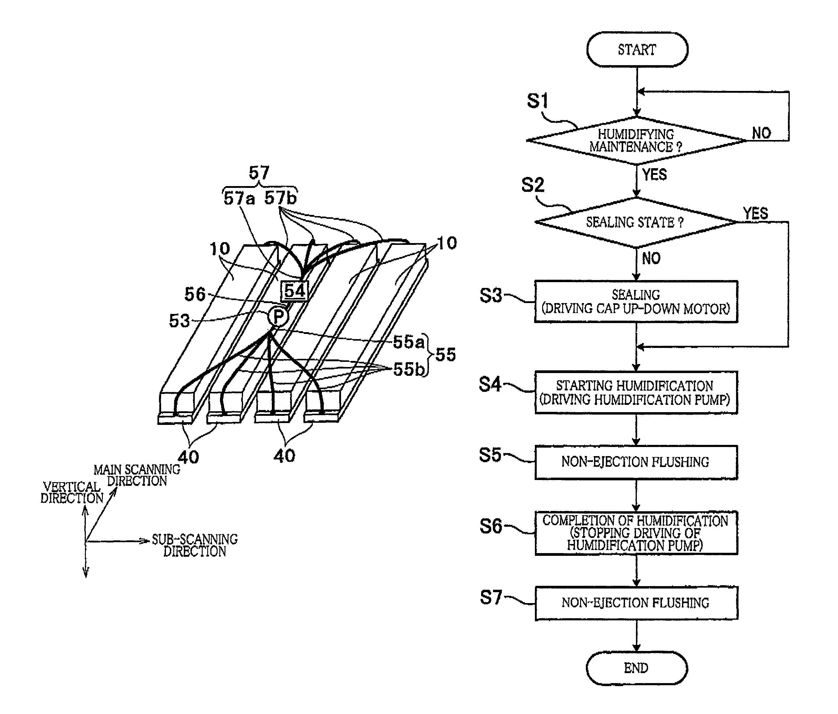
[0025]In the space A, there are arranged four heads 10, a conveyance mechanism 21, a guide unit, a controller 1p, a humidifying mechanism 50 (see FIG. 5), and so on.

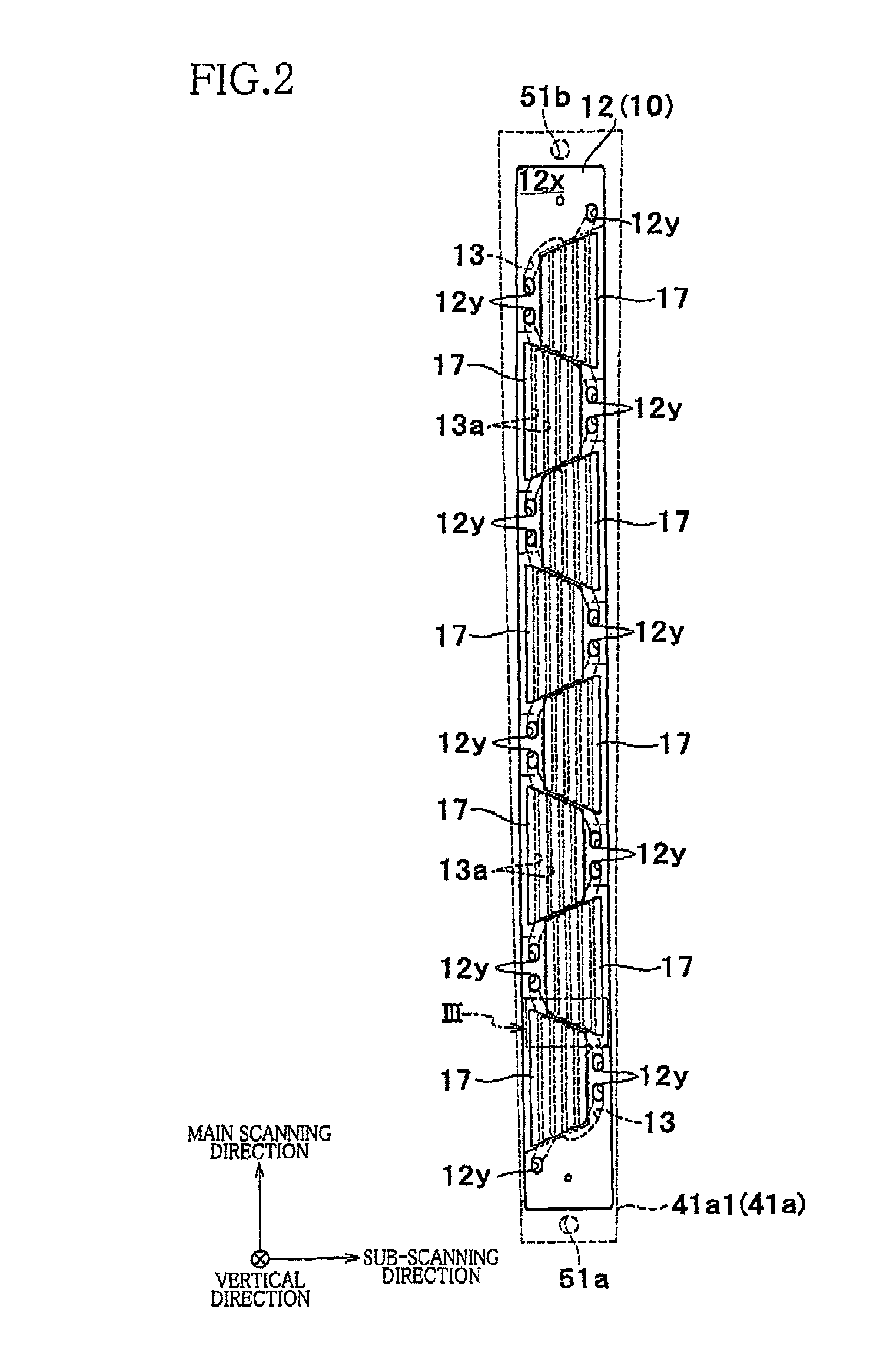
[0026]Each of the heads 10 is a line head having a generally rectangular parallelepiped shape elongated in a main scanning direction in which each head 10 r...


PUM


Abstract

A liquid ejection apparatus including: a head having an ejection face having ejection openings through which liquid is ejected, an ejection space being defined so as to face the ejection face; a sealing mechanism configured to selectively establish a sealing state for sealing the ejection space and an unsealing state; a humid-air supply mechanism configured to supply humid air into the ejection space in the sealing state; and a controller. The controller controls the humid-air supply mechanism to humidify the ejection space such that a humidity in the ejection space becomes equal to or higher than a predetermined humidity. The controller controls the head to perform a non-ejection flushing in at least one of a humidification period in which the humid-air supply mechanism humidifies the ejection space and a post-humidification period that extends for a first period from a completion of the humidification.

Description

CROSS REFERENCE TO RELATED APPLICATION[0001]The present application claims priority from Japanese Patent Application No. 2011-017874, which was filed on Jan. 31, 2011, the disclosure of which is herein incorporated by reference in its entirety.BACKGROUND OF THE INVENTION[0002]1. Field of the Invention[0003]The present invention relates to a liquid ejection apparatus configured to eject liquid such as ink, a controller for controlling the apparatus, and a nonvolatile storage medium storing a program for controlling the apparatus.[0004]2. Description of the Related Art[0005]An ink-jet printer as one example of a liquid ejection apparatus includes an ink jet head (liquid ejection head) having a multiplicity of ejection openings through which liquid such as ink is ejected to record an image on a recording medium. Here, a viscosity of the liquid in the head may increase by vaporization of water (water content) of the liquid via the ejection openings. This increase in the viscosity of the...

Claims


Application Information

Patent Timeline
Patent Type & Authority Patents(United States)
IPC IPC(8): B41J29/38B41J2/165B41J2/18
CPCB41J2/18B41J2/165
Inventor TAMAKI, SHUICHI
Owner BROTHER KOGYO KK
Learn More