Terminal fitting and method of producing it
a technology of terminal fittings and fittings, applied in the direction of coupling contact members, coupling device connections, electrical devices, etc., can solve the problems of excessive resilient reaction force applied to the male tab from the resilient piece, and difficult to ensure a space for arranging the excessive resilient deformation of the preventing pieces on the base wall. to achieve the effect of preventing excessive resilient deformation
- Summary
- Abstract
- Description
- Claims
- Application Information
AI Technical Summary
Benefits of technology
Problems solved by technology
Method used
Image
Examples
first embodiment
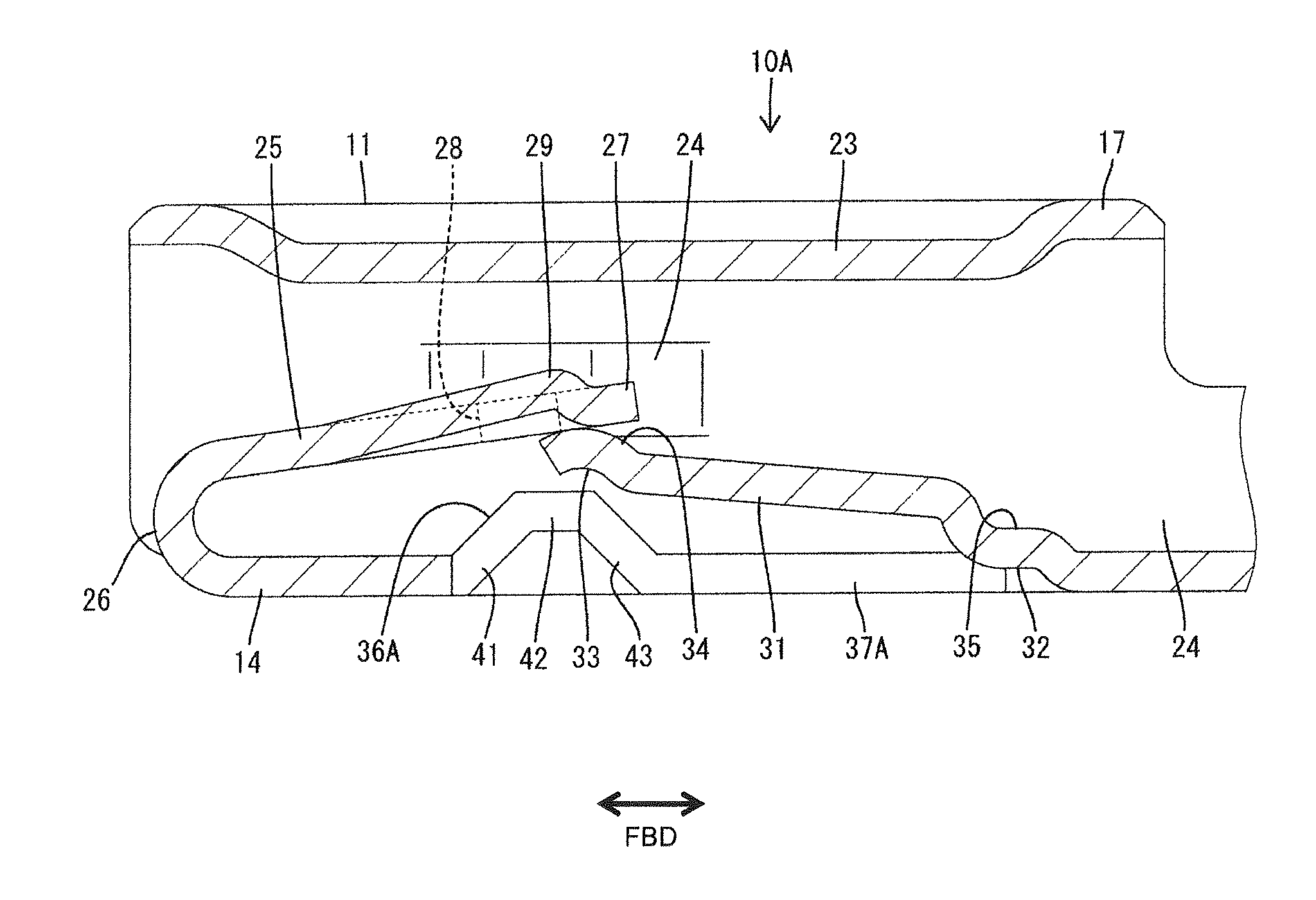
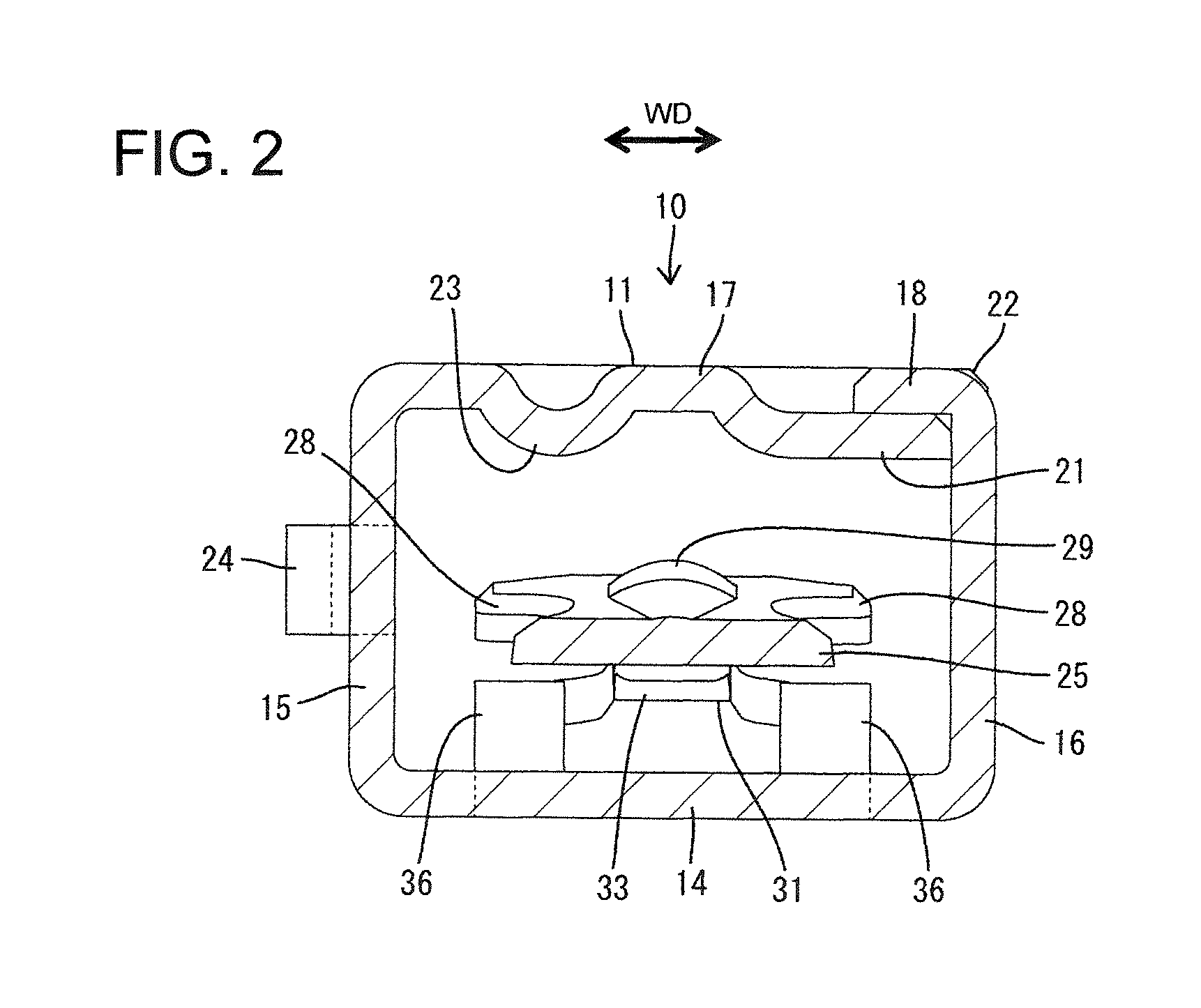
[0090]The excessive deformation preventing pieces 36 of the first embodiment project from the base wall 14. Thus, the surface of the first spring piece 25 that faces the base wall 14 stably contacts the excessive deformation preventing pieces 36 before the first spring piece 25 is deformed excessively and the contact is at locations on the first spring piece 25 to prevent warping deformation. The second spring piece 31 is narrower than the first spring piece 25. Thus, a space for the excessive deformation preventing pieces 36 is ensured by arranging the excessive deformation preventing pieces 36 adjacent opposite widthwise sides of the second spring piece 31
[0091]The punched hole 37 penetrates the base wall 14 and both the second spring piece 31 and the excessive deformation preventing pieces 36 are formed by bending parts of the base wall 14 defining the punched hole 37. Thus, it is not necessary to form separate punched holes for the second spring piece 31 and for the excessive de...
third embodiment
[0104]the invention is described with reference to FIGS. 10 to 13. A terminal fitting 110 of this embodiment is formed by bending, folding and / or embossing an electrically conductive metal plate and includes a main portion 120, a wire barrel 160 to be connected to a wire 190 and a first resilient piece 140.
[0105]As shown in FIG. 10, the barrel 160 is on the rear of the terminal fitting 110 and comprises a wire barrel 161 to be crimped, folded or bent into connection with an exposed end portion of a core 191 of a wire 190 and at least one insulation barrel 162 behind the wire barrel 16 to be crimped, folded or bent into connection with an insulation coating 192 near the end of the wire 190.
[0106]The main portion 120 is a substantially rectangular tube and, as shown in FIGS. 11 and 12, has a substantially flat bottom plate 121 connected to and extending from the wire barrel 160. Side plates 122 project up from opposite widthwise sides of the bottom plate 121 and a ceiling plate 123 ex...
fourth embodiment
[0120]the invention is described with reference to FIGS. 14 to 20. A terminal fitting T according to the fourth embodiment is accommodated in a housing 201. As shown in FIG. 20, cavities 202 are formed in upper and lower levels in the housing 201 and penetrate the housing 201 in forward and backward directions. The terminal fitting T is insertable into the cavity 202 from behind and a mating terminal fitting 227 is insertable therein from the front. A resiliently deformable locking lance 203 is formed in each cavity 202 and can deform in a direction substantially perpendicular to an inserting direction of the terminal fitting T. The outer surface of a substantially rectangular tube 204 of the terminal fitting T slides in contact with the locking lance 203 and resiliently deforms the locking lance 203 in the process of inserting the terminal fitting T. The locking lance 203 passes over the rectangular tube 204 and resiliently restores when the terminal fitting T is inserted to a prop...
PUM
 Abstract
Description
Claims
Application Information
 - R&D
- Intellectual Property
- Life Sciences
- Materials
- Tech Scout
- Unparalleled Data Quality
- Higher Quality Content
- 60% Fewer Hallucinations
Browse by: Latest US Patents, China's latest patents, Technical Efficacy Thesaurus, Application Domain, Technology Topic, Popular Technical Reports.
© 2025 PatSnap. All rights reserved.Legal|Privacy policy|Modern Slavery Act Transparency Statement|Sitemap|About US| Contact US: help@patsnap.com


