Dispenser for media

Inactive Publication Date: 2010-06-01
APTAR RADOLFZELL
View PDF14 Cites 9 Cited by
  • Summary
  • Abstract
  • Description
  • Claims
  • Application Information

AI Technical Summary

Benefits of technology

[0009]In the second variant the circumstances are similar to those of the first variant, but are modified in that the locking profiling associated with the pump casing, instead of the locking profiling of the functional section, has a radial, elastic resilience. Once again the elastic resilience can be brought about by an adapted geometry or material design. The locking profiling can either be directly part of the pump casing or can be firmly connected to the latter. As in the first variant a securing section is provided and is located on the inside or outside of the locking profiling associated with the pump casing, the securing section once again being provided on the side opposite to the locking profiling of the functional section. In the case of locking profilings which are pressed outwards during the assembly process, the securing section is provided in the form of an outside securing section and in the case of locking profilings which are pressed inwards during the assembly process the securing section is provided as an inside securing section. As in the first variant, the securing section prevents an elastic deformation of the pump casing-side locking profiling, so that it is made much more difficult to remove the functional section from the pump casing. Unlike in the first variant, the securing section is not entrained with the functional section and instead remains connected in stationary manner to the pump casing. The connection between pump casing and securing section is preferably provided in non-positive and / or positive form.
[0010]The dispenser according to the invention, in the case of the two variants according to the invention, is secured in constructionally simple manner against undesired disassembly.
[0012]Thus, the stop shoulder is at least partly constructed in such a way that the pump longitudinal axis is perpendicular thereto. A planar stop shoulder oriented in this way constitutes a particularly good stop which reliably and in defined manner limits the pump lift. It is particularly advantageous that when the functional section strikes against the pump casing in the upper lift end position, as a result of this design of the stop faces only axial forces are transmitted, which reduces the risk of the locking profilings being radially deformed when the functional section strikes hard against the upper lift end position, because such a radial deformation would allow the functional section to slide off the pump casing. This makes it possible to achieve an improved dosing precision. Preferably the corresponding locking profilings, particularly the detents or support studs, are provided with correspondingly radially oriented support or stop faces so as to allow a reliable, axial supporting of the functional section on the pump casing.
[0017]Apart from the dispenser for media, the invention also relates to an assembly method for a dispenser, particularly a dispenser in the first variant according to the invention. The assembly method more generally relates to dispensers with a pump casing and an applicator displaceable in a limited axial manner with respect to the pump casing in operation. In a first assembly step a hollow profile-shaped securing section is engaged on the pump casing and then in a second assembly step the applicator is mounted on the pump casing with the securing section, the securing section and applicator engaging with one another in such a way that the securing section and applicator are positively and / or non-positively interconnected and together prevent the applicator from being drawn off.
[0018]In the first assembly step the securing section is preferably displaced up to a pump casing-side stop on the pump casing. In the second assembly step the applicator is preferably once again moved up to a pump casing-side stop on the pump casing, said pump casing-side stop preferably simultaneously defining the lift end position in pump operation. During the engagement of the applicator the latter is connected to the securing section, so that in pump operation the applicator and securing section are jointly guided on the pump casing. As a result of this connection between the securing section and the applicator there is preferably a reduction in the resilience of one of the two parts following engagement necessary for the engagement of the securing section or applicator, so that the removal of the applicator from the pump casing requires a much greater force than the engagement on said pump casing. As a result of the method according to the invention a particularly simple plug assembly is made possible.

Problems solved by technology

Thus, a very high force and which may possibly damage the pump components is necessary to slide the locking profiling of the functional section secured by the securing section over the corresponding locking profiling associated with the pump casing.
In addition, a bending moment acting on the functional section about a pump transverse action is scarcely suitable in the case of a locking profiling of the functional section secured in this way for releasing the functional section from the pump casing.

Method used


Image

  • Dispenser for media
  • Dispenser for media
  • Dispenser for media

Examples


first embodiment

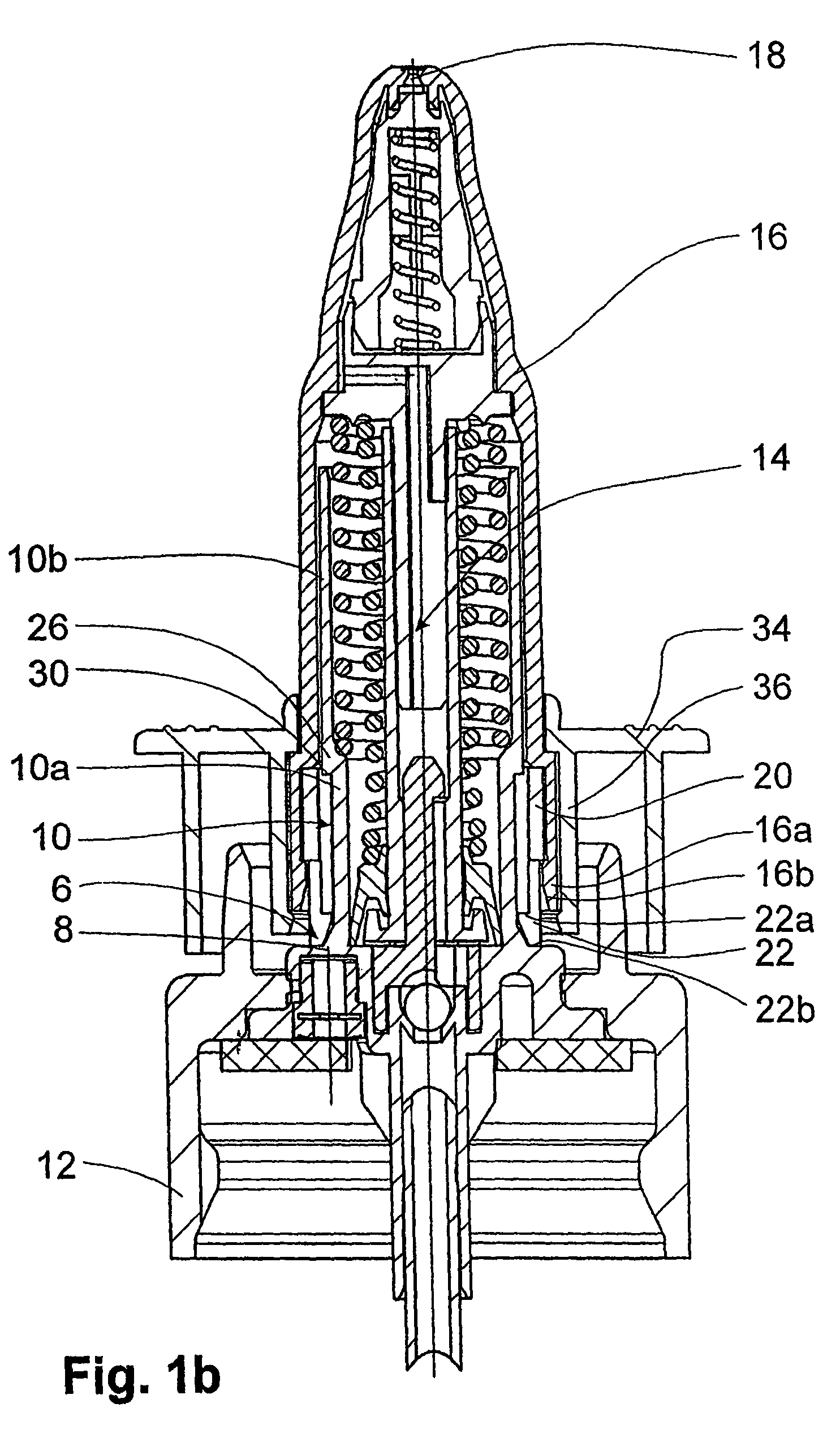
[0025]FIGS. 1a and 1b show a dispenser according to the invention. The dispenser has a substantially rotationally symmetrical pump casing 6 comprising a casing base 8 and a cylindrical section 10. The pump casing 6 is connected to a closure 12 for mounting on a media container. In an inner area 14 of the pump casing 6 are provided a series of pump components used for delivering the medium contained in the not shown media container. Onto the cylindrical section 10 of the pump casing 6 is mounted an applicator 16 provided on its upper side with a discharge opening 18. The applicator 16 is connected by means of an applicator-side locking profiling 16b with a functional section 20 by which the applicator is connected to the pump casing 6 in such a way that it is axially displaceable between the upper lift end position shown in FIG. 1a and the lower lift end position shown in FIG. 1b. To this end the functional section 20 has six detents 22 which extend radially inwards. Each pair of cir...

second embodiment

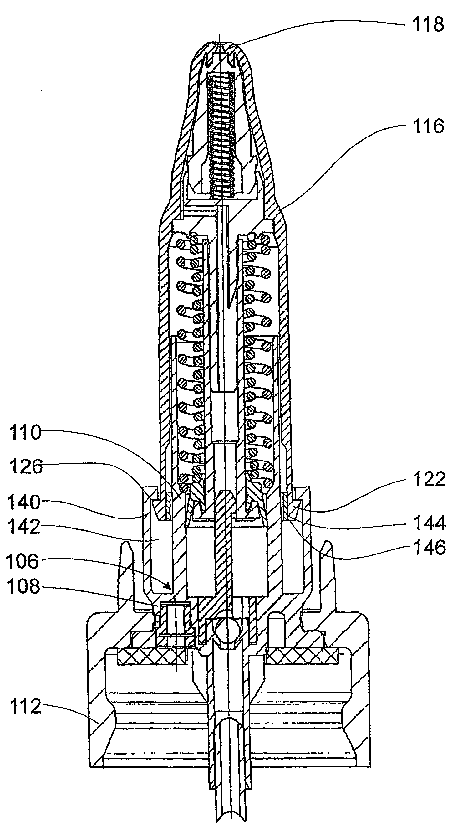
[0029]FIG. 2 shows the media dispenser according to the invention. As in the case of the dispenser shown in FIGS. 1a and 1b, it has a pump casing 106 onto which is engaged an applicator 116 with a discharge opening 118. On the applicator 116 are provided at the lower end detents 122 integrally connected to said applicator and which extend radially outwards. Adjacent pairs of detents 122 are separated from one another by a cut 122a (FIG. 4a). The locking profiling on the side of the pump casing 106 corresponding to the detents 122 is constituted by a circumferential annular shoulder 126 at the upper end of a cylindrical auxiliary web 140 extending axially upwards from a casing base 108. The cylindrical section 110 of the pump casing 106 together with the auxiliary web 140 forms a circumferential, one-sided axially open chamber 142 into which project the detents 122 of applicator 116. Within the chamber 142 the detents 122 are engaged on a cylindrical Securing section 144 having an ex...


PUM


Abstract

A dispenser for discharging media, particularly liquids, foams and pastes is proposed and whose dispenser casing is secured against dismantling. A securing section is provided which is engaged on the pump casing separately from a functional section. The securing section is connected by positive or frictional engagement with the functional section and in the joined state limits a first locking profiling provided on the functional section with regards to its elastic resilience, so that a second locking profiling provided on the pump casing and corresponding with the locking profiling of the functional section can no longer be overcome for dismantling purposes.

Description

CROSS REFERENCE TO RELATED APPLICATION[0001]The following disclosure is based on German Patent Application No. 102005009296.9 filed on Feb. 22, 2005, which is herewith incorporated into this application by explicit reference.FIELD OF THE INVENTION[0002]The invention relates to a dispenser for media having a pump with an inside pump casing on which is displaceably guided coaxially to a pump longitudinal axis and in limited manner at least one hollow profile-shaped functional section, the displaceability in at least one direction being limited by axially mutually cooperating and mutually corresponding locking profilings, as well as to an assembly method for such a dispenser.BACKGROUND OF THE INVENTION[0003]Such dispensers are in particular used for liquids, suspensions, pastes and foams and are employed for the dosed discharge of said media. Preferably such dispensers are operated manually and in particular an applicator with a discharge opening guided coaxially to the pump casing can...

Claims


Application Information

Patent Timeline
IPC IPC(8): G01F11/00
CPCB05B11/3042B05B11/3039B05B11/3001B05B11/3049B05B11/1001B05B11/1039B05B11/1049B05B11/1042
Inventor GREINER-PERTH, JUERGEN
Owner APTAR RADOLFZELL
Why Eureka
Try Eureka