
Sheet feeding device and recording apparatus

a feeding device and recording device technology, applied in the direction of thin material handling, article separation, function indicators, etc., can solve the problems of difficult to separate papers, difficult to separate recording media, and inability to set such a relation between resistances, so as to reduce the separating resistance in separating recording media, and reduce the separating resistance.

Active Publication Date: 2014-12-02
CANON KK
View PDF12 Cites 2 Cited by
  • Summary
  • Abstract
  • Description
  • Claims
  • Application Information

AI Technical Summary

Benefits of technology

The present invention focuses on the idea that it can regulate how well a separating member moves along an inclined surface when trying to separate recording media. This is done by exerting a larger separating resistance when a recording medium has low rigidity, and a smaller separating resistance when a medium has high rigidity. This results in stable separation, regardless of the amount of recording media present. The technical effect of this invention is better and more effective separation of recording media.

Problems solved by technology

For example, since the plain papers have the low rigidity, it is difficult to separate the papers one by one, but since the photograph sheets have the high rigidity, the sheets can easily be separated one by one.
It is not easy to separate the recording media having the different characteristics one by one in this way by use of a common sheet feeding device of an inclined surface separation system.
Therefore, it is not possible to set such a relation between the resistances as to enable the suitable separation of any recording media.
In the constitution where the member moves along the inclined surface, however, it is not possible to create such a difference of the frictions as to assure the separating operations of the recording media having the different characteristics.
In consequence, the relation between the resistances changes in accordance with a stack position, and even when the same type of recording media are separated, the media cannot suitably be separated.
Moreover, when the photograph sheets are used as the recording media, there is a possibility that an excessively large resistance is applied to a front edge of each photograph sheet that comes in contact with the separating member to peel off the coating surface of the photograph sheet, if the separating resistance is not suitably set.
For example, when the photograph sheets are used in this recording apparatus, the separating member abuts on a recording surface (the coating surface), and hence there is also a possibility that the coating surface is damaged, when an unsuitable resistance is applied.

Method used


Image

  • Sheet feeding device and recording apparatus
  • Sheet feeding device and recording apparatus
  • Sheet feeding device and recording apparatus

Examples


embodiment 1

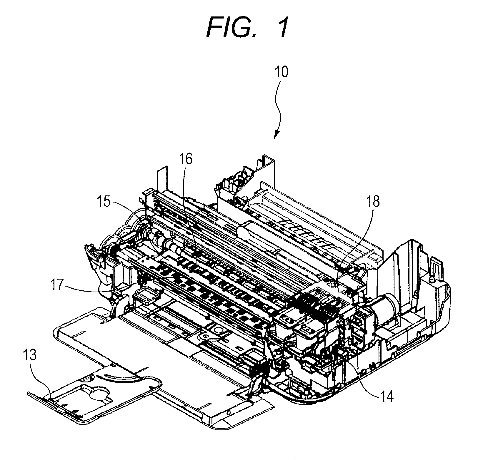
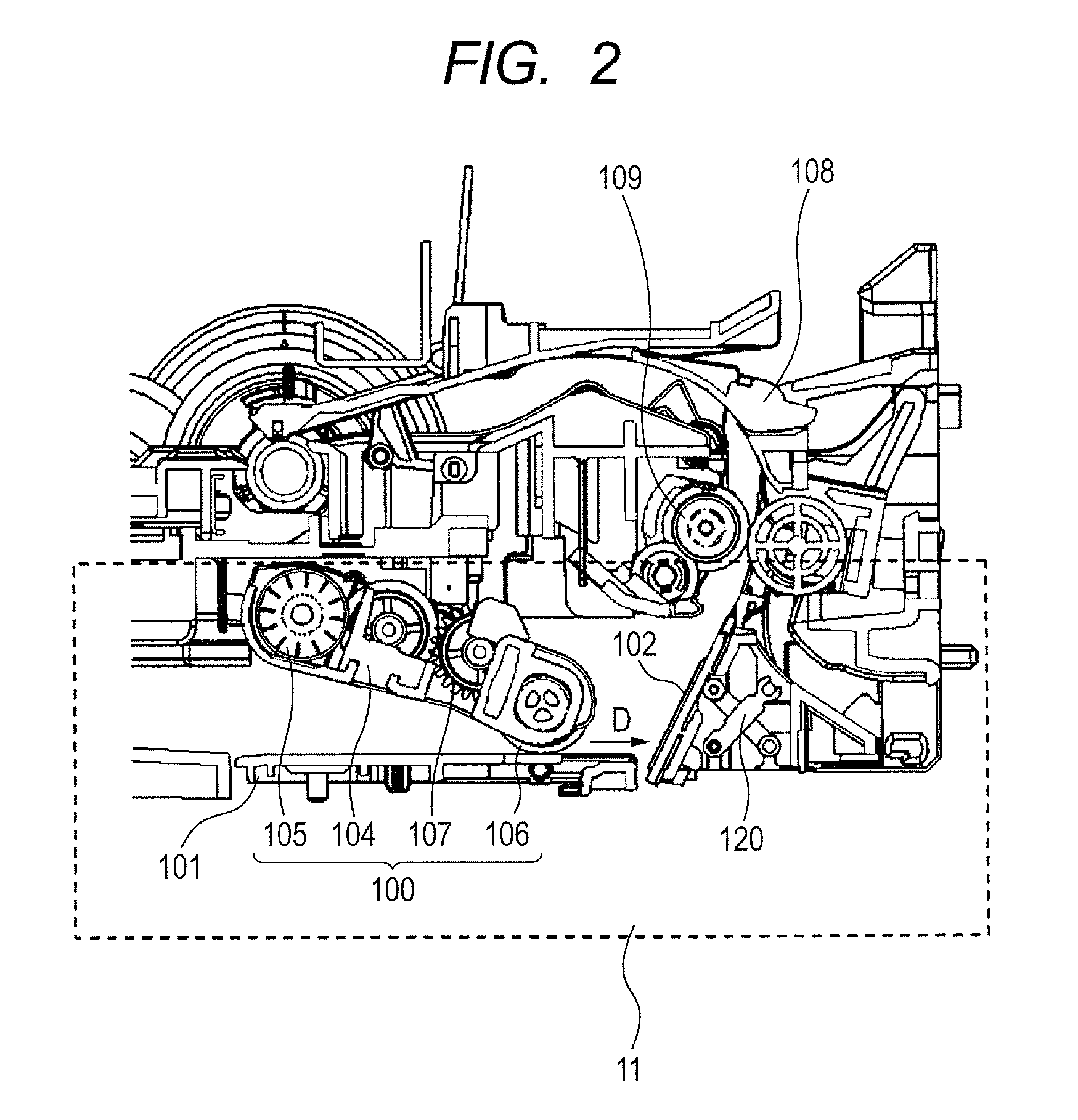
[0031]FIG. 1 is a perspective view showing an inner constitution of an ink jet recording apparatus 10 which is an embodiment of a recording apparatus of the present invention. FIG. 1 mainly shows a constitution of an image forming section which records an image on each recording medium. The image forming section is constituted of a recording head 14, a platen 15, a pair of main conveying rollers 16, a sheet discharge roller 17, a carriage 18, and the like. In the ink jet recording apparatus 10 shown in FIG. 1, each recording medium fed from a sheet feeding device (not shown: description will be made later in detail) disposed in a bottom surface of the apparatus passes through a conveying path (not shown) positioned in a rear part of the recording apparatus and curved in a U-shape, and the medium is conveyed to the platen 15. Afterward, the recording head 14 discharges ink to record the image on the recording medium while scanning along the platen 15. At this time, the recording head...

embodiment 2

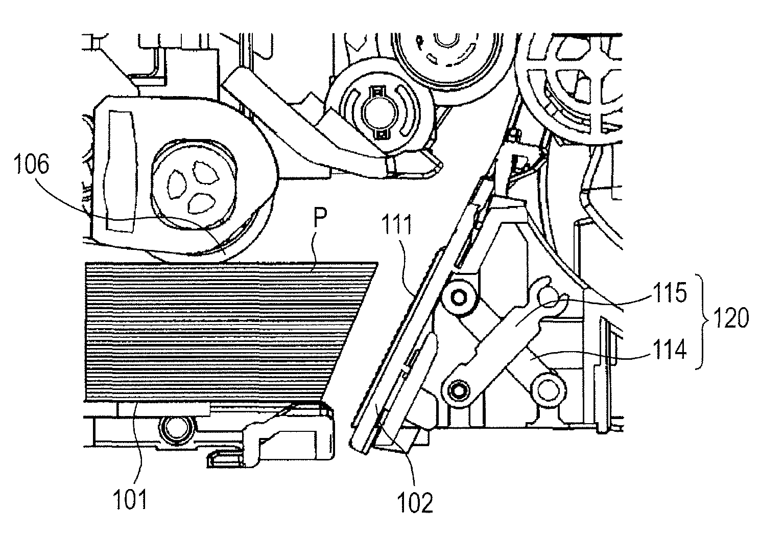
[0051]A recording apparatus of the present embodiment will be described. In the recording apparatus of the present embodiment, a constitution of a link mechanism 120 is different from that in the above ink jet recording apparatus 10 of Embodiment 1. Hereinafter, the constitution of the link mechanism 120 will be described in detail.

[0052]FIG. 13 is a sectional view showing the constitution of the link mechanism 120 disposed in an ink jet recording apparatus of the present embodiment. In the present embodiment, a link member 114 and a link member 115 having an equal length are arranged. One end of each of the link members 114 and 115 is attached to a separating member 111. On the other hand, the other end of each of the link members 114 and 115 is rotatably attached to an inclined surface member 102.

[0053]In the present embodiment, the link member 114 and the link member 115 support the separating member 111 at a projecting position, in an inclined state at an angle φ to a traveling ...


PUM

PropertyMeasurementUnit
forceaaaaaaaaaa
elastic forceaaaaaaaaaa
rigidityaaaaaaaaaa

Abstract

There is disclosed a sheet feeding device which feeds a plurality of stacked sheet-like recording media one by one from a tray containing the recording media, including a sheet feeding roller which comes in contact with the uppermost layer of the recording media contained in the tray, and rotates to feed the recording medium; an inclined member including an inclined surface which is positioned on a downstream side in a feeding direction of the recording media, and inclined at an obtuse angle to the feeding direction of the recording media, and on which the fed recording media abuts; and a separating member having an uneven surface, to separate the one fed recording medium, wherein the separating member is configured to be movable between a position projecting to the inclined member and a position retreated from the projecting position, while maintaining the same inclining angle as that of the inclined member.

Description

BACKGROUND OF THE INVENTION[0001]1. Field of the Invention[0002]The present invention relates to a sheet feeding device which separates and conveys stacked recording media one by one, and a recording apparatus on which the sheet feeding device is mounted.[0003]2. Description of the Related Art[0004]A recording apparatus such as a printer, a photocopying machine or a facsimile machine includes a sheet feeding device which stacks and contains a plurality of recording media in a sheet feeding tray, and separates and feeds the stacked and contained recording media one by one. As separation systems for the recording media in the sheet feeding device, many constitutions have been suggested, and as one of the constitutions, an inclined surface separation system is known where a front edge of each recording medium is made to abut on a separating member disposed on an inclined surface which is inclined to a traveling direction of the recording media, thereby separating the recording media. T...

Claims


Application Information

Patent Timeline
Patent Type & Authority Patents(United States)
IPC IPC(8): B65H3/52B65H3/06B65H3/56
CPCB65H2405/1134B65H2402/344B65H3/56B65H2301/4222B65H2405/1136B65H2515/81B65H2405/142B65H3/0684B65H2403/53B65H2511/22B65H2402/30B65H2220/01B65H2220/08
Inventor HAKAMATA, KEISEI
Owner CANON KK
Learn More