Metal nanopillars for surface-enhanced Raman spectroscopy (SERS) substrate and method for preparing same

a raman spectroscopy and surface-enhanced technology, applied in the direction of spectrometry/spectrophotometry/monochromators, instruments, optical radiation measurement, etc., can solve the problem that the raman spectroscope is still more expensive than infra-red spectroscopy and limits its application

Active Publication Date: 2014-11-25
PHANSCO +1
View PDF2 Cites 6 Cited by
  • Summary
  • Abstract
  • Description
  • Claims
  • Application Information

AI Technical Summary

Problems solved by technology

However, the relatively minuteness of cross section of molecule beam making the detection of Raman signals difficult causes replacement of this technology by near-infrared spectroscopy (NIRS).
But the Raman spectroscope is still more expensive than infra-red spectroscopy limiting its application.

Method used


Image

  • Metal nanopillars for surface-enhanced Raman spectroscopy (SERS) substrate and method for preparing same
  • Metal nanopillars for surface-enhanced Raman spectroscopy (SERS) substrate and method for preparing same
  • Metal nanopillars for surface-enhanced Raman spectroscopy (SERS) substrate and method for preparing same

Examples


embodiment

Preferred Embodiment

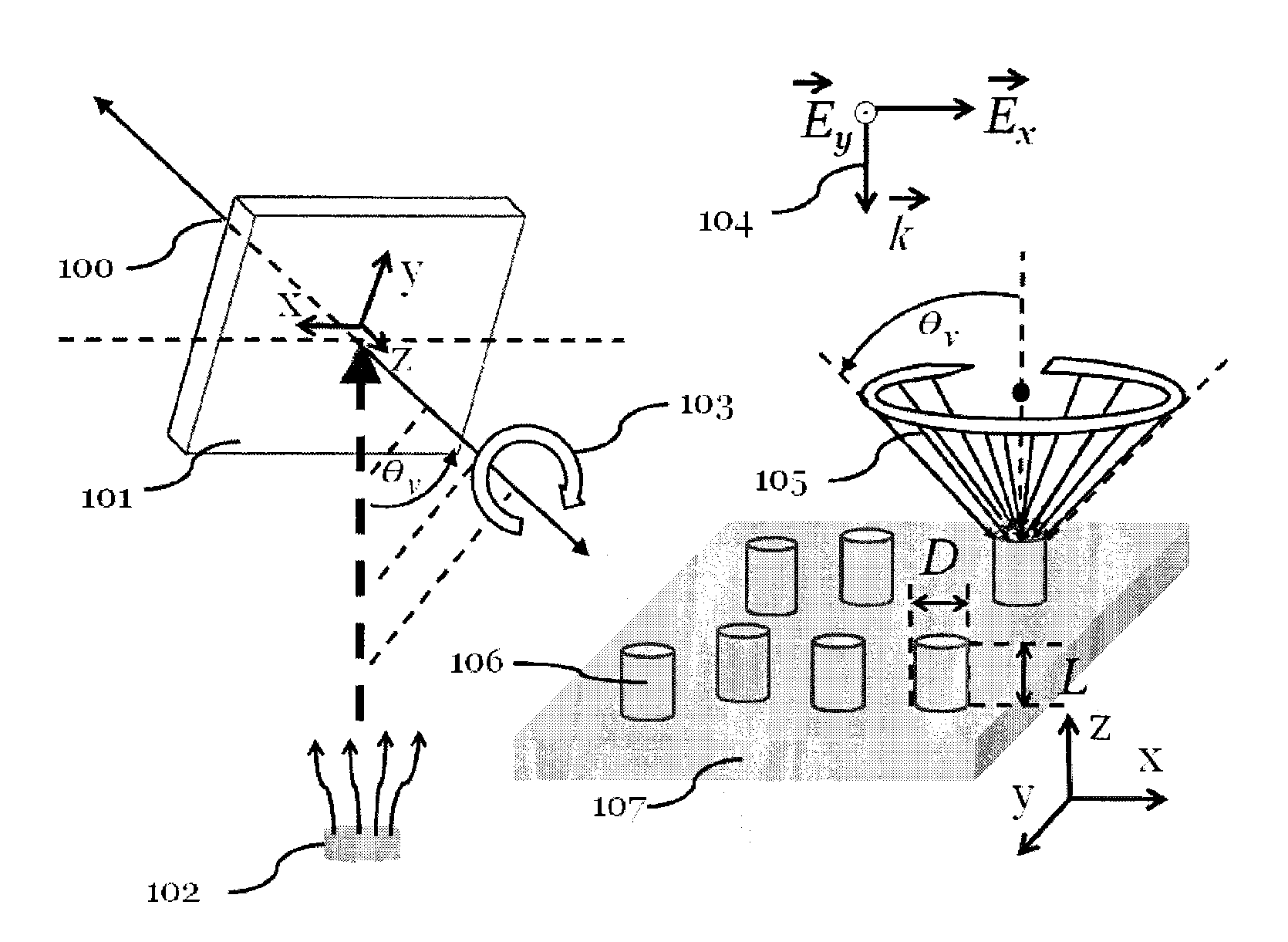
[0040]The FIG. 3(a) is used again for following reiterations. In an exemplified manufacturing process, the silver particles of 3 mm diameter of purity 99.999% are adopted as evaporation source 102 and the electron beam gun evaporation system is maintained at base pressure of 4×10⁻⁶ Pa. During deposition, the substrate is rotated about the axis of substrate normal line at a constant speed. The lengths of the pillars are controlled by using a quartz thickness monitor placed next to the substrate. The deposition rate is maintained and the deposition angle is kept at θv.

[0041]FIG. 2(a), (c), (e), (g) are respectively the top view diagrams taken by scanning electron microscope (SEM) for deposition speed=1.2 nm / s, θv=89 degrees, collocating with four types of substrate rotation speed of 20 rpm, 10 rpm, 1 rpm and 0.1 rpm, wherein in FIG. 2(a), (c), (e) nanopillar L=120 nm, and in FIG. 2(g) the nanopillar is L=250 nm.

[0042]FIG. 2(b), (d), (f), (h) respectively shows, at ...


PUM

PropertyMeasurementUnit
heightaaaaaaaaaa
diameteraaaaaaaaaa
speedaaaaaaaaaa

Abstract

Disclosed herein describes an SERS sensing substrate comprising upright metal nanostructures made by using oblique angle deposition (OAD) collocating with self-rotation substrate, wherein said upright nanostructures include individual upright nanopillars and metal / dielectric multilayered upright nanopillar stacks. The SERS sensing substrate exhibits higher and enhanced adsorption spectra for unpolarized incident rays in the visible and infrared wavelength regimes.

Description

CROSS-REFERENCE TO RELATED APPLICATION[0001]This utility application claims priority to Taiwan application serial number 101101168, filed on Jan. 12, 2012, that is incorporated herein by reference.BACKGROUND OF THE DISCLOSURE[0002]1. Field of the Disclosure[0003]The invention relates to a surface enhanced Raman spectroscopy (SERS) sensing substrate and the manufacturing method thereof for enhancing Raman signals of specimen to be sensed.[0004]2. Brief Description of the Related Art[0005]Raman in 1928 invented the Raman scattering method that utilizes scattering property of light for detecting the vibrational spectroscopy signals (Raman spectroscopy) of molecule. However, the relatively minuteness of cross section of molecule beam making the detection of Raman signals difficult causes replacement of this technology by near-infrared spectroscopy (NIRS).[0006]After the lasers were invented in the 1960, the lasers have been used as excitation source in Raman spectroscopy since 1964 for ...

Claims


Application Information

Patent Timeline
Patent Type & Authority Patents(United States)
IPC IPC(8): C23C14/22C23C14/14B05D5/06G01N21/65G01Q70/16
CPCG01N21/658C23C14/14C23C14/226B05D5/061Y10T428/12535Y10T428/24355
Inventor JEN, YI-JUNYU, CHING-WEI
Owner PHANSCO
Why Eureka
Try Eureka