
Device for manufacturing a fabric, and fabric

a fabric and fabric technology, applied in the field of fabric manufacturing devices, can solve the problems of creased fabrics that cannot be further processed with limitations, cannot meet the requirements of creased fabrics, so as to achieve uniform tension distribution over the width of the fabric, and maintain constant tension distribution over the width.

Active Publication Date: 2014-11-25
GEBR KLOCKER
View PDF20 Cites 2 Cited by
  • Summary
  • Abstract
  • Description
  • Claims
  • Application Information

AI Technical Summary

Benefits of technology

The invention relates to a fabric manufacturing process using a leno weave apparatus. The process allows for the binding of a weft thread at different times in different regions of the fabric to achieve a more even tension distribution. The apparatus can also be arranged staggered to further reduce the possibility of movement of the weft thread. The resulting fabric has a more uniform tension distribution and larger porosity. The invention also includes a process for binding the weft thread with a different number of interlacings in the edge region of the fabric to achieve a constant tension distribution. Overall, the invention improves the quality and efficiency of fabric manufacturing.

Problems solved by technology

Such a fabric in accordance with the prior art also does not lie taut on the beam of the fabric take-off in the edge region, which can result in creasing in the edge region.
Creased fabrics can only be further processed with limitations.
The weft thread in this respect has more time to yield toward the center of the fabric, which thus results in a homogenized distribution of tension over the width of the fabric.

Method used


Image

  • Device for manufacturing a fabric, and fabric
  • Device for manufacturing a fabric, and fabric
  • Device for manufacturing a fabric, and fabric

Examples


Embodiment Construction

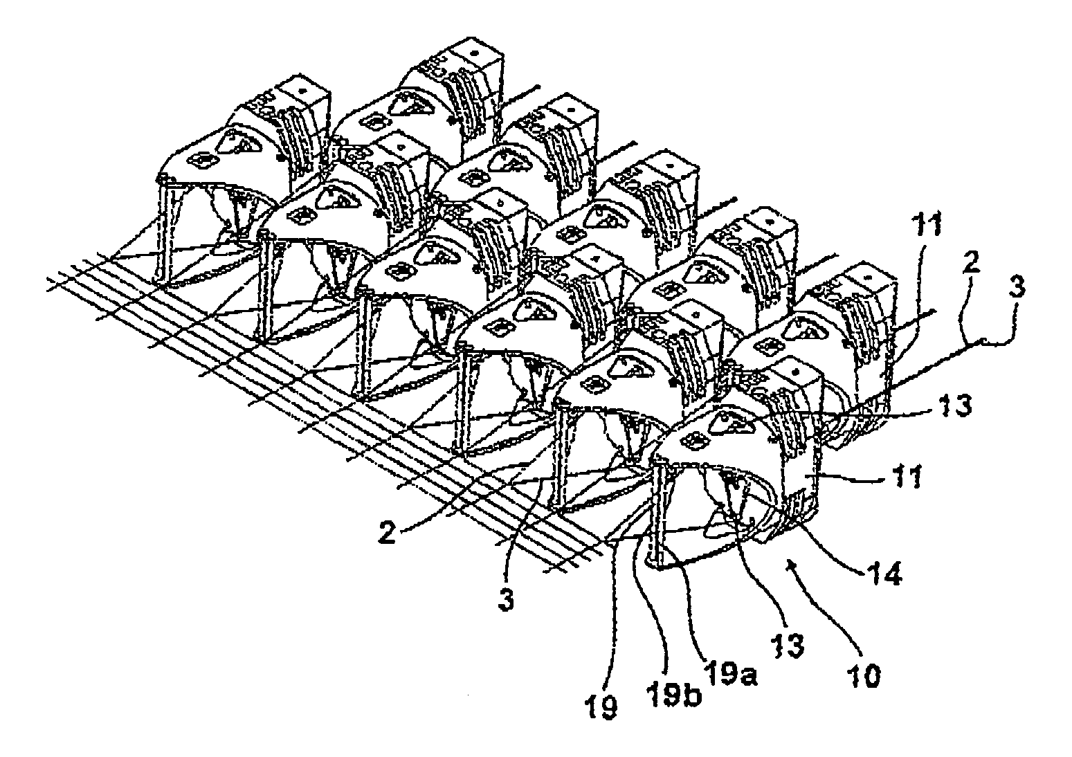
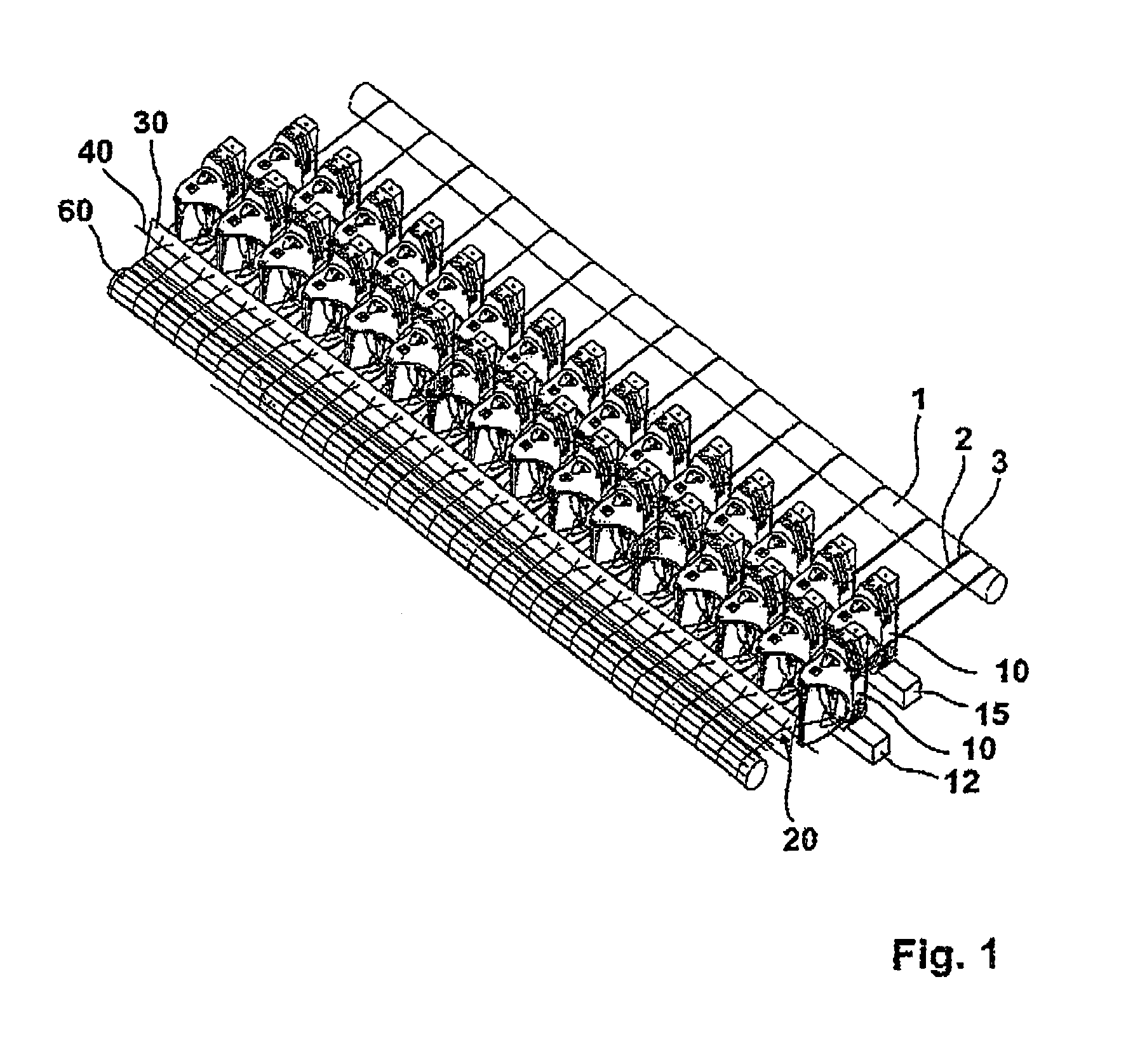
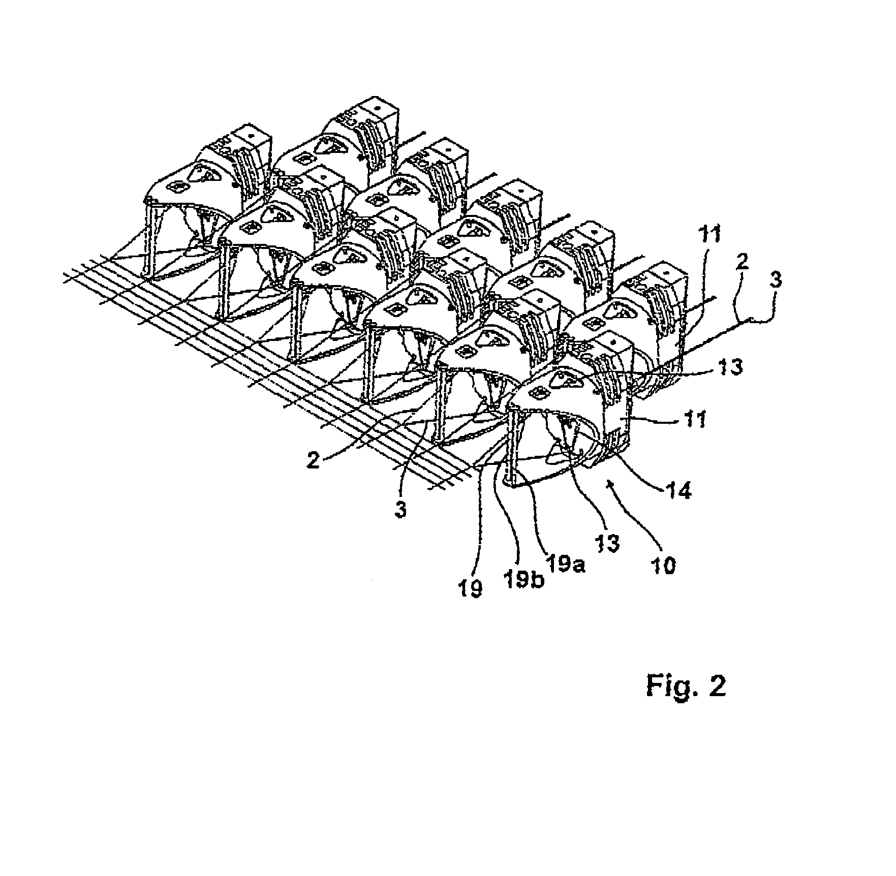
[0028]The two leno threads 2 and 3 are located on the warp beam. It is, however, also conceivable to provide reels for the reception of the leno threads. The leno threads 2 and 3 are supplied to the leno weave apparatus shown at 10. A plurality of such leno weave apparatus 10 are arranged next to one another over the width of the fabric on a first carrier 12. A second carrier 15 likewise has leno weave apparatus 10 arranged thereon and is located at the same height in parallel to the first carrier 12. The leno weave apparatus 10 on the two carriers have the same design in principle. There is a spacing between the leno weave apparatus 10 arranged on the first carrier 12, with the spacing being such that the leno web apparatus 10 arranged on the carrier 15 are likewise able to form a shed in the gap between two respective leno weave apparatus 10 on the first carrier 12. This means that space must also remain for the rotation of the propeller. It has already been pointed out that the l...


PUM


Abstract

A device for manufacturing a fabric has a plurality of automatically working apparatus arranged next to one another on at least one carrier for manufacturing a leno weave (a leno weave apparatus). Two leno threads are fed to each leno weave apparatus. The device has at least one weft thread picking device; wherein the weft thread is introduced into the shed of leno threads raised by a plurality of leno weave apparatus. The weft thread is bound using at least two leno threads at a plurality of points behind the weft thread over the width of the fabric. At least one of the leno weave apparatus arranged in the end region of the fabric carries out a higher number of interlacings for achieving a homogenized warp tension distribution over the width of the fabric; and / or the lowering of the shed is carried out by the leno weave apparatus over the width of the fabric at different times for achieving a homogenized warp tension distribution.

Description

CROSS REFERENCE TO RELATED APPLICATION[0001]This U.S. patent application claims priority from German patent application Serial No. DE 102012009420.5, filed May 11, 2012, the content of which is incorporated herein in its entirety.FIELD OF THE INVENTION[0002]The invention relates to a device for manufacturing a fabric and to a fabric.BACKGROUND OF THE INVENTION[0003]Such devices for fabric manufacture are known as conventional looms. Such a loom comprises a plurality of heddle shafts driven in opposite directions, wherein a plurality of heddles are arranged beside one another ON the heddle shafts, with the warp threads running off the warp beam being guided through the heddles. The shafts run in opposite directions to one another so that a shed is raised by the heddles with the warp threads guided therein on such an oppositely directed movement of the shafts. A weft thread is guided through this raised shed, for example by means of rapiers or also by means of air. Such machines are t...

Claims


Application Information

Patent Timeline
Patent Type & Authority Patents(United States)
IPC IPC(8): D03C7/08D03D19/00D03C7/00D03C7/06D03C13/00
CPCD03C7/06D03C7/08D03D19/00
Inventor HOCKEMEYER, KURTSCHWEMMLEIN, CHRISTOPH
Owner GEBR KLOCKER
Learn More