
Electro-mechanical fuze for hand grenades

a technology of electronic mechanical and hand grenades, which is applied in the field of electronic mechanical safety fuzes, can solve the problems of inability to store for an extended period of time, unfavorable safety hazards, and the ability to unintendedly initiate the device,

Inactive Publication Date: 2014-11-18
UNITED STATES OF AMERICA THE AS REPRESENTED BY THE SEC OF THE ARMY
View PDF14 Cites 16 Cited by
  • Summary
  • Abstract
  • Description
  • Claims
  • Application Information

AI Technical Summary

Benefits of technology

The present invention describes an electro-mechanical fuze that improves reliability and safety for use in military hand grenades. It incorporates interrelated mechanical and electronic safety logic, an initially out-of-line firetrain, and electronic timing. The fuze also includes a safety and arming device with a moveable component that isolates all primer sensitive explosives from being in-line with the secondary insensitive detonating explosives. The safety and arming device is initiated when armed, builds from a deflagrating spot charge to a detonating output, and allows for increased safety of the hand grenade during storage, transport, and scenarios not intended to cause function.

Problems solved by technology

Some of the current hand grenades employ a simple chemical powder delay column to effect a timing delay before function, which is permanently in-line with a primer explosive element and a detonator / high explosive fill, creating a potential safety hazard and the ability for unintended initiation of the device.
In addition, this method of fuzing does not offer a very accurate, repeatable delay time across many units, due to hygroscopic effects on the powder and poorly controlled delay column densities.
However, these mechanical delay fuzes present numerous inherent problems, including but not limited to: the inability to be stored for an extended period of time, inconsistent timing to detonation, dependency on temperature, susceptibility to aging, subject to manufacturing inaccuracy.
Even though these electric time delay circuits have proven to be more reliable than their mechanical counterparts, they in turn, present inherent disadvantages.
As an example, the electric time delay mechanisms are predisposed to unintended electrical activation, that can lead to the premature and unintentional detonation of the hand grenade.

Method used


Image

  • Electro-mechanical fuze for hand grenades
  • Electro-mechanical fuze for hand grenades
  • Electro-mechanical fuze for hand grenades

Examples


Embodiment Construction

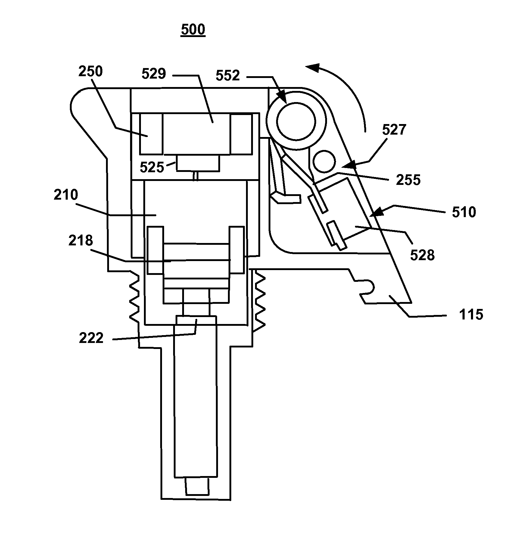
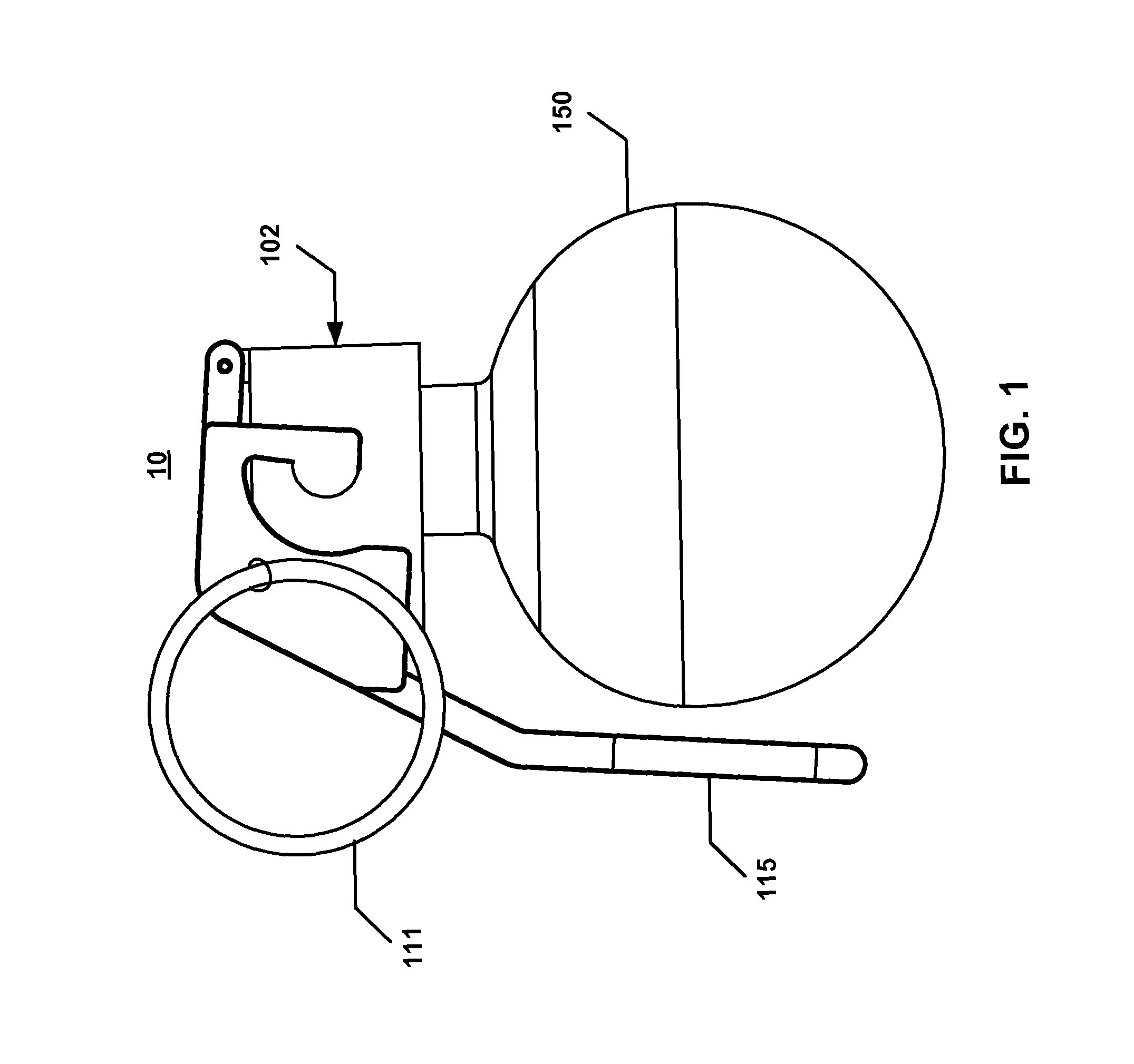
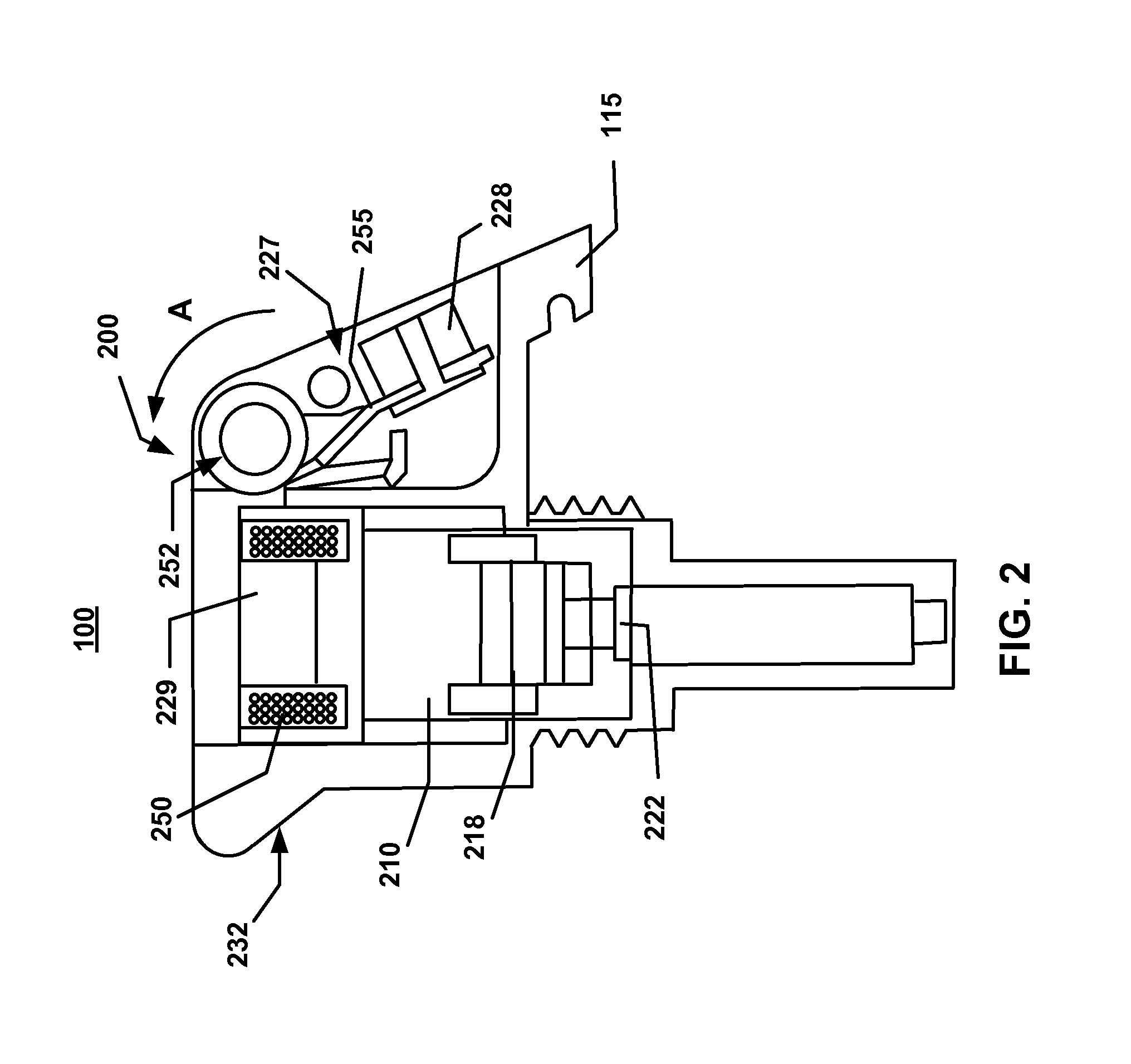
[0031]FIG. 1 illustrates a hand grenade 10 that incorporates an electro-mechanical fuze 100 (FIGS. 2, 3) of the present invention. In addition to the added safety measures, the fuze 100 can be readily integrated in a conventional or available striker body 102 in a way that is transparent to the end user, in terms of appearance, means of operation, performance, and handling characteristics. This transparent integration is important in that it does not necessitate changes to the training regimen on the use of the hand grenade 10.

[0032]In this example and with further reference to FIG. 2, the hand grenade 10 generally includes a fuze 100 which is secured to a grenade body 150, as well as manual safety devices, such as a safety pin 111 and a safety lever 115 that are secured to a fuze body 102. The hand grenade 10 contains and houses the fuze 100, so that its presence is transparent to the user.

[0033]In a preferred embodiment, FIG. 2, the fuze 100 includes a power generation source, suc...


PUM


Abstract

A safety fuze includes a magneto striker generator (MSG) as its a power generation source. The MSG provides energy to energize an electronic unit and a safety and arming device. The safety fuze allows safety and arming of military hand grenades, with a fully out-of-line explosive initiator and an integrated power generation means, for improving safety and performance. The MSG includes a striker and a receiving bobbin that houses a conductive coil. The striker comprises a permanent magnet that is mounted on a pivot mechanism for allowing a rotational displacement of the permanent magnet, into the bobbin, in order to generate an electrical current. As the permanent magnet is being inserted inside the bobbin, the magnetic flux change induces an electric current in the coil, creating the necessary energy for the fuze operation.

Description

GOVERNMENTAL INTEREST[0001]The invention described herein may be manufactured and used by, or for the Government of the United States for governmental purposes without the payment of any royalties thereon.FIELD OF THE INVENTION[0002]The present invention relates in general to the field of munitions. More specifically, this invention relates to electro-mechanical safety fuzes for hand emplaced grenades for military and commercial uses. In particular, the present electro-mechanical safety fuze allows safety and arming of military hand grenades, with a fully out-of-line explosive initiator and an integrated power generation means, for improving safety and performance.BACKGROUND OF THE INVENTION[0003]Safety is a very important design aspect of a hand grenade fuze. Fuze designs account for a time delay period from initiation, for the detonation to occur, in order to ensure that the grenade is cast outside the explosion hazard area. As a result, it is essential that this time delay does n...

Claims


Application Information

Patent Timeline
Patent Type & Authority Patents(United States)
IPC IPC(8): F42C11/02F24C15/20F42C15/20F42B27/00F42C14/02F42C15/40F42C11/06F42C11/00
CPCF42C15/20F42C14/025F42C15/40F42C11/06F42B27/00F42C11/02F42C11/003F42C11/008F42C15/18
Inventor KNIGHT, RYAN R.BARHAM, OLIVER M.HOANG, THINH Q.WOOD, ROBERT H.
Owner UNITED STATES OF AMERICA THE AS REPRESENTED BY THE SEC OF THE ARMY
Learn More