
Optical spectrum analyzer actuated by voice coil

Inactive Publication Date: 2014-11-11
OPTOPLEX CORP
View PDF5 Cites 0 Cited by
  • Summary
  • Abstract
  • Description
  • Claims
  • Application Information

AI Technical Summary

Benefits of technology

This patent is about a device that uses a voice coil actuator to speed up the operation of an optical spectrum analyzer. The device includes an optical filter, a detector, and a voice coil actuator that causes the filter to rotate in a back-and-forth motion, changing the wavelength of light it receives. An encoder synchronizes the movement of the filter with the wavelength received by the detector. Compared to traditional devices, this invention is faster and smaller. Other embodiments may use a diffraction grating instead of a multilayer-coating filter, or an oscillating mirror reflecting toward a stationary filter and detector. The use of a moving filter or plate helps keep the light in the desired direction. The invention has various advantages, such as faster operation and smaller size.

Problems solved by technology

It is noted that an implementation based on an oscillating mirror reflecting toward a stationary filter and a detector is not practical because with a moving mirror it is extremely difficult to maintain the reflected beam in a predetermined direction.

Method used


Image

  • Optical spectrum analyzer actuated by voice coil
  • Optical spectrum analyzer actuated by voice coil
  • Optical spectrum analyzer actuated by voice coil

Examples


Embodiment Construction

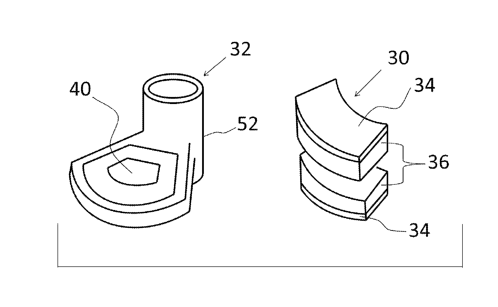
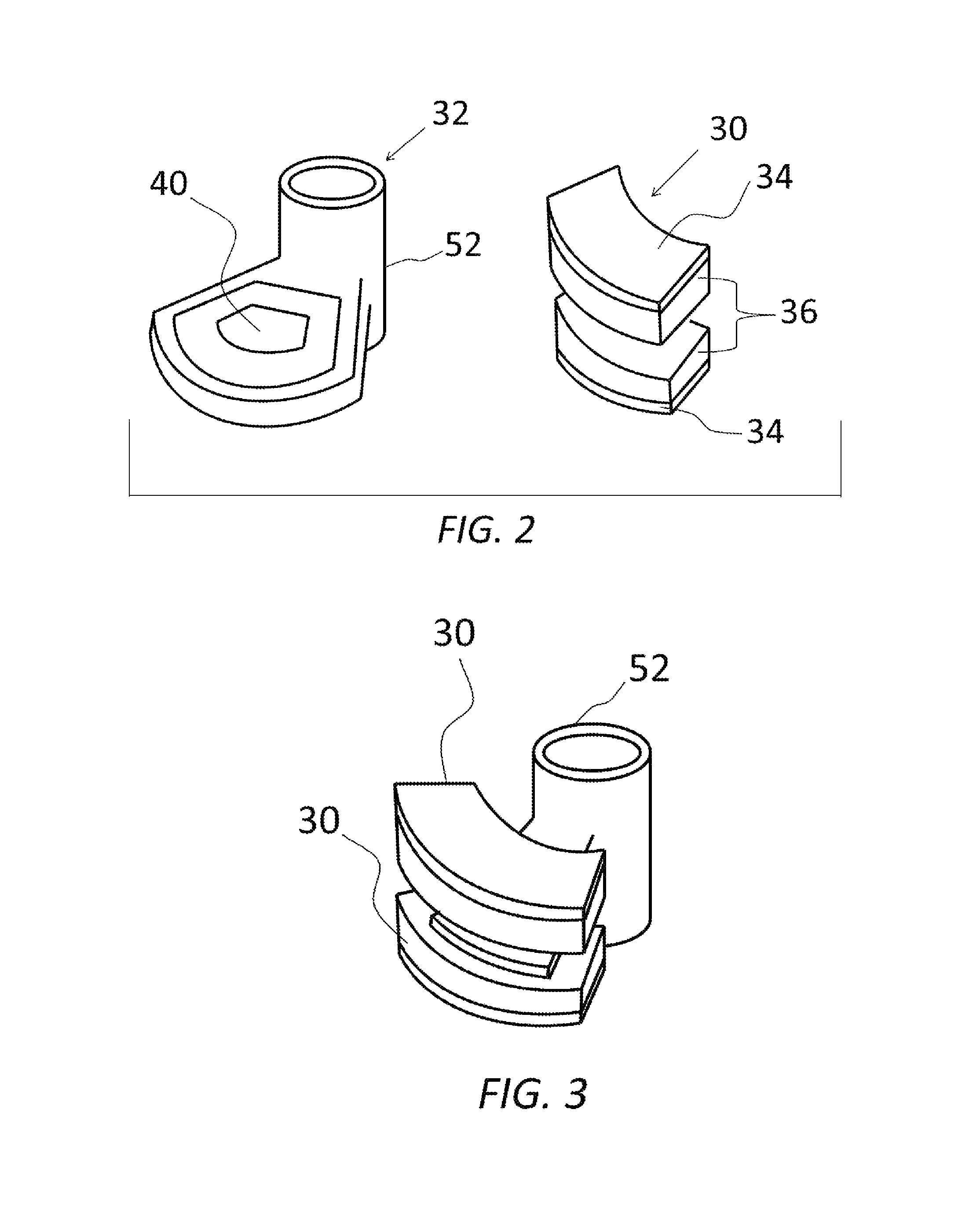
[0019]The idea of this invention is to replace the BLDC motor with a computer-drive voice-coil actuator. The term voice coil is commonly used to refer to the coil of wire that moves the read-write heads in a moving-head disk drive. Accordingly, the terms “voice coil” and “voice coil actuator” (VCA) are herein also so defined for the purposes of the invention.

[0020]Such a voice coil actuator is a very simple positioning device, in essence a motor, that utilizes a coil of wire in a permanent magnetic field. As illustrated in the exploded view of FIG. 2 and in FIG. 3, it consists of two separate parts: a stationary magnetic component 30 and a movable coil component 32. The magnetic component consists of two opposite poles, each made of a nickel-plated iron plate 34 with a strong rare-earth permanent magnet 36 attached to it, with a gap between them, so as to create a magnetic field with substantially vertical lines of flux between the magnets. The coil component consists of a very ligh...


PUM


Abstract

An optical spectrum analyzer includes a multilayer-coating filter for separating a wavelength in the spectrum of an incident input beam, a detector optically coupled to the filter, a voice-coil actuator for rotating the filter in oscillating motion to vary the wavelength received by the detector as a function of time, and an encoder for synchronizing the angular position of the filter with the wavelength received at the detector. The use of the voice-coil actuator makes it possible to achieve significantly greater speeds of operation with a significantly smaller device.

Description

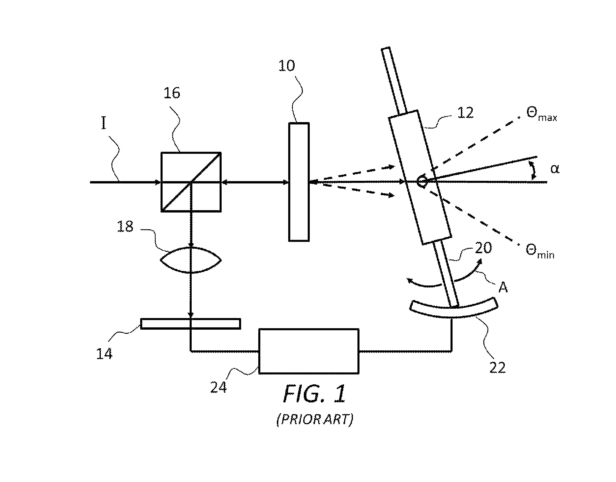
RELATED APPLICATIONS[0001]This application is based on and claims the priority of U.S. Provisional Application Ser. No. 61 / 486,209, filed May 13, 2011.BACKGROUND OF THE INVENTION[0002]1. Field of the Invention[0003]This invention pertains to the general field of optical spectrum analyzers, especially as used in communication networks. In particular, the invention relates to an optical spectrum analyzer with a novel implementation of the continuously oscillating scanning mechanism.[0004]2. Description of the Prior Art[0005]Optical spectrum analyzers (often referred to in the art as OSAs) are usually implemented using multilayer-coating filters and diffraction gratings. As illustrated schematically in FIG. 1, in conventional diffraction grating applications a portion of the input beam I is combined with a diffraction grating 10 to separate different wavelengths and direct them in respective separate directions. A mirror 12 is used to reflect a portion of the diffracted spectrum back t...

Claims


Application Information

Patent Timeline
IPC IPC(8): G01J3/00
CPCG01J3/00G01J3/06G01J3/12G01J2003/064G01J2003/1243
Inventor HSIEH, YUNG-CHIEH
Owner OPTOPLEX CORP
Learn More