Logic circuit

a logic circuit and circuit technology, applied in logic circuits, pulse counters, computation using non-denominational number representations, etc., can solve problems such as large silicon area

Inactive Publication Date: 2005-06-21
FORTE DESIGN SYSTEMS
View PDF42 Cites 2 Cited by
  • Summary
  • Abstract
  • Description
  • Claims
  • Application Information

AI Technical Summary

Benefits of technology

[0020]Embodiments of the present invention have several advantages over the prior art. The use of non-hierarchical multiplexers (muxes), built from pass-gates, as switching components has the advantage of achieving greater speed of evaluation, and reducing the silicon area needed to implement the circuit. It also provides a greater ease of layout compared with previous methods.
[0024]The circuit may include a third subcircuit to generate a function such as a selection function or threshold function. One of the functions outputted by the third subcircuit may be selected by the second subcircuit according to the number of high inputs in the first set of binary inputs. Selection may be configured such that the output of the third subcircuit reflects the total number of high inputs to both the first and the third subcircuits. This has the advantage that instead of one subcircuit having to deal with a large number of inputs, the total number of inputs to be counted can be split between a plurality of subcircuits, and the logic provided in each subcircuit can thus be more straightforward.
[0025]The total number of inputs may be divided yet further by employing a circuit with a tree-like structure, where a plurality of first and third subcircuits are provided at the first level of the tree structure, and each of these passes its outputs to a second subcircuit to generate an intermediate count signal. The intermediate count signals are passed to the second level of the tree structure, where they are summed by further first, second and third subcircuits. Thus, selection functions <kj> or threshold functions [k,j] or other functions relating to a count of the number of high inputs may be generated easily for high values of k. This has application in a parallel counter circuit which generates a binary representation of the number of high signals on its inputs.

Problems solved by technology

These circuits often appear on the frequency-limiting paths of systems and can consume large silicon area, and much importance is placed on achieving speed and area improvements in their implementation.

Method used


Image

  • Logic circuit
  • Logic circuit
  • Logic circuit

Examples


first embodiment

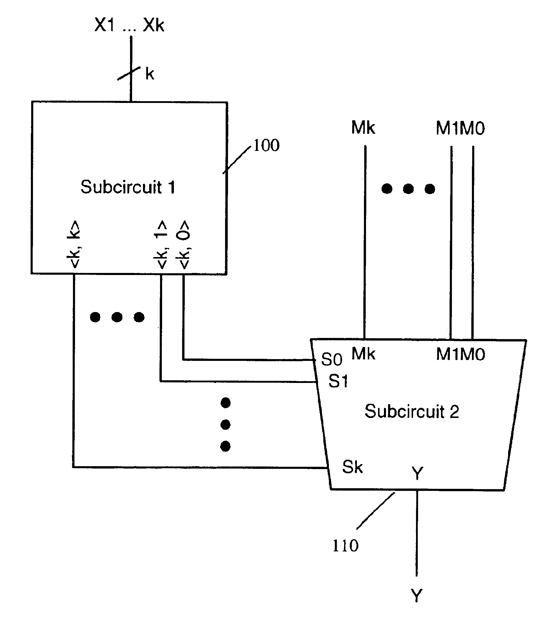
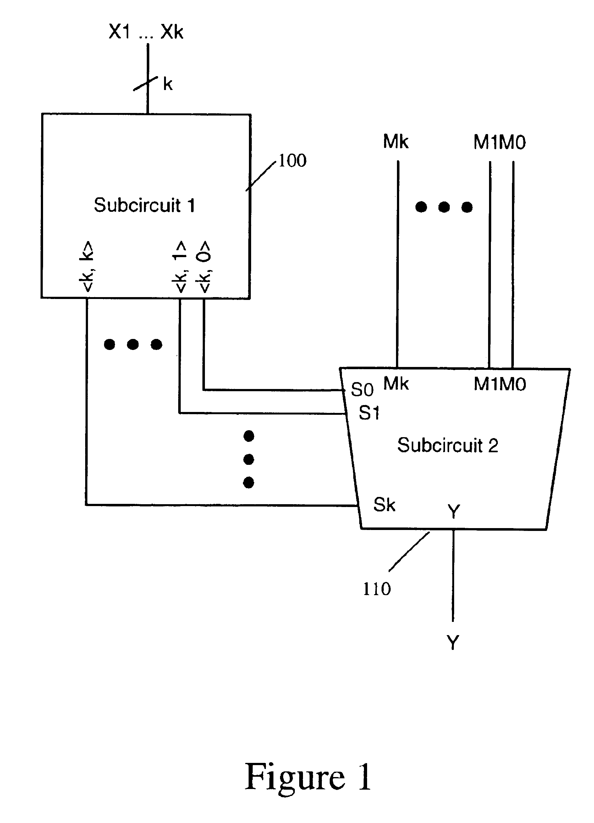
[0037]FIG. 1 is a block diagram of a circuit according to the invention.

[0038]The circuit selects one of a plurality of binary inputs M0, . . . ,Mk, depending on the number of highs amongst a further plurality of binary inputs X1, . . . ,Xk. The circuit has two subcircuits: a first subcircuit 100 and a second subcircuit 110.

[0039]The first subcircuit 100 determines the number of highs amongst the further plurality of binary inputs, X1, . . . Xk. There are a total of k binary inputs X1, . . . ,Xk to subcircuit 100. Subcircuit 100 generates k+1 outputs, consisting of a series of selection functions , where j is an integer between 0 and k. Each selection function outputs a high value if there are exactly j high inputs amongst the k inputs to subcircuit 100, and outputs a low value if there are less than or greater than j high inputs amongst the k inputs to subcircuit 100. Each of the selection functions from j=0 to j=k is generated as a separate output signal, giving k+1 output signals...

second embodiment

[0051]FIG. 4 shows a block diagram of a circuit according to the invention. This circuit has k inputs, and generates the selection function 2>, which indicates whether or not exactly two of the k inputs are high. The inputs are divided into two separate groups of inputs, X1, . . . ,Xk1 and Y1, . . . ,Yk2. The first group has k1 inputs, and the second group has k2 inputs, such that the total number of inputs k=k1+k2.

[0052]The circuit of FIG. 4 includes a subcircuit 300, a subcircuit 305, and a subcircuit 310. The subcircuit 300 is similar to the first subcircuit 100 of FIG. 1, but has k1 inputs X1, . . . ,Xk1 and generates k1+1 output signals 1,0> to 1,k1>, each indicating whether or not a particular number of the inputs X1, . . . ,Xk1 are high.

[0053]The subcircuit 305 has k2 inputs Y1, . . . ,Yk2. Subcircuit 305 also generates functions to indicate whether or not a given number of highs are present on the inputs. However, unlike in subcircuit 300, instead of all of the functions 2,0...


PUM


Abstract

Circuit for selecting a second set of binary inputs according to the number of high input signals applied to a first input set. A first subcircuit has the first input set, logic generating control output signals, each control output signal represents whether the first input set has exactly a predetermined number of high input signals. Each control output signal corresponds to a different predetermined number of high input signals. A second subcircuit has a second input set, a set of control inputs for receiving control output signals from the first subcircuit, and logic including a plurality of switches including one or more pass gates. Each switching component switches to connect or isolate one of the second input set to a common output. The control inputs control the switches. The first and second subcircuits are configured such that only one switch can be switched to connect at a time.

Description

RELATED APPLICATION[0001]This application claims priority under 35 U.S.C 119(e) from U.S. Provisional Application Ser. No. 60 / 439,852 filed Jan. 14, 2003, which application is incorporated herein by reference.FIELD OF THE INVENTION[0002]The present invention relates to digital electronic devices, and in particular, to a digital electronic device performing binary logic.BACKGROUND TO THE INVENTION[0003]A fundamental requirement in digital electronics is a circuit which, depending on the number of highs amongst a second plurality of inputs, selects one of a first plurality of inputs. Such a circuit can be provided to indicate if the number of highs amongst k inputs belongs to any particular subset of the integers {0, 1, . . . , k}.[0004]Examples of such circuits include threshold circuits, which indicate if j or more of k total inputs are high. The threshold function [k,j] is low if there are less than j high inputs within k total inputs, but [k,j] is high if there are j or more high ...

Claims


Application Information

Patent Timeline
Patent Type & Authority Patents(United States)
IPC IPC(8): G06F7/60H03K19/173
CPCH03K19/1737G06F7/607
Inventor WHITE, BENJAMIN EARLE
Owner FORTE DESIGN SYSTEMS
Why Eureka
Try Eureka