Method and apparatus for determining spacecraft maneuvers

a technology for spacecraft and maneuvers, applied in process and machine control, instruments, navigation instruments, etc., can solve problems such as violations of operational constraints, and achieve the effect of reducing expenditur

Inactive Publication Date: 2014-11-04
THE UNITED STATES OF AMERICA AS REPRESENTED BY THE SECRETARY OF THE NAVY
View PDF21 Cites 49 Cited by
  • Summary
  • Abstract
  • Description
  • Claims
  • Application Information

AI Technical Summary

Problems solved by technology

Thus, operational constraints can be violated when such maneuvers are implemented on orbit.

Method used


Image

  • Method and apparatus for determining spacecraft maneuvers
  • Method and apparatus for determining spacecraft maneuvers
  • Method and apparatus for determining spacecraft maneuvers

Examples


Embodiment Construction

[0030]One or more embodiments or implementations are set forth in conjunction with the drawings, where like reference numerals refer to like elements throughout, and where the various features are not necessarily drawn to scale. Control apparatus and methods are presented for guiding or maneuvering CMG-equipped spacecraft to transition from an initial state to a desired final state, wherein the disclosed concepts find utility in association with satellites, manned spacecraft, or any other form of spacecraft or vehicle.

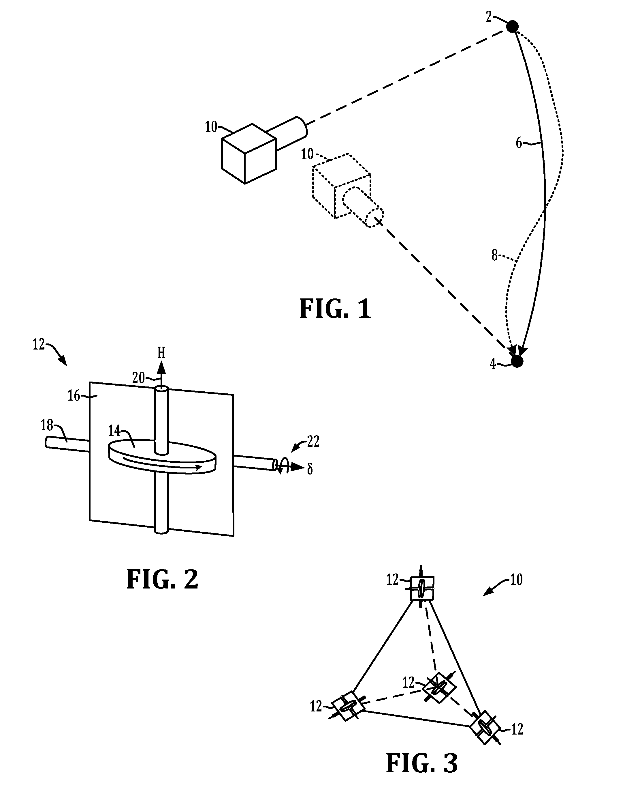
[0031]Referring initially to FIGS. 1-3, an exemplary CMG-equipped spacecraft 10 is illustrated undergoing such a maneuver between initial and final positions or attitudes. FIG. 1 illustrates an exemplary spacecraft 10 in a first position in which a telescope or camera thereof is aligned to obtain images of a first reference point 2, as well as in a second position (shown in dashed lines in the figure) with the telescope facing a second reference point 4. FIG. 1 further...


PUM


Abstract

Methods and apparatus are presented for spacecraft operation in which a control problem is formulated using a control law or steering law as a path constraint or as a dynamic constraint, and the control problem is solved to provide a guidance command trajectory for use in operating spacecraft control momentum gyroscopes to guide the spacecraft from an initial state to a desired final state.

Description

REFERENCE TO RELATED APPLICATION[0001]This application claims priority to and the benefit of U.S. Provisional Patent Application Ser. No. 61 / 691,896, filed Aug. 22, 2012, and entitled “METHOD FOR DETERMINING OPTIMIZED SPACECRAFT MANEUVERS”, the entirety of which is hereby incorporated by reference.BACKGROUND[0002]The present disclosure relates to control of the attitude or orientation of spacecraft, for example, to position a telescope mounted to a satellite to obtain an image of an object by reorienting the satellite itself. A typical spacecraft is equipped with a group or array of three or more control moment gyroscopes (CMGs) to facilitate attitude control of the vehicle. Spacecraft attitude control techniques commonly involve Eigen axis rotations. Eigen axis rotations are desirable as they are intuitively simple to construct and provide the advantage of reorienting the spacecraft along the shortest circular arc between the starting and desired final attitude angles. The angular ...

Claims


Application Information

Patent Timeline
Patent Type & Authority Patents(United States)
IPC IPC(8): G05D1/08B64G1/28B64G1/36B64G1/24
CPCB64G1/24B64G1/288B64G1/36B64G1/286B64G2001/245B64G1/245B64G1/369
Inventor KARPENKO, MARKROSS, ISAAC MICHAEL
Owner THE UNITED STATES OF AMERICA AS REPRESENTED BY THE SECRETARY OF THE NAVY
Why Eureka
Try Eureka