Automatic water leveler

a technology of automatic water leveler and water leveler, which is applied in the direction of valve operating means/release devices, machines/engines, bends, etc., can solve the problems of time-consuming and costly procedure for installing automatic water levelers in pre-existing pool decks or walls, additional cost and complexity associated with the installation of electric automatic water levelers when compared, and achieves easy adjustment, quick and easy adjustment of water level, and small resistance

Inactive Publication Date: 2014-11-04
LARSEN DAVID
View PDF22 Cites 2 Cited by
  • Summary
  • Abstract
  • Description
  • Claims
  • Application Information

AI Technical Summary

Benefits of technology

[0010]The design of the ball check valve represents another significant improvement when compared to check valves incorporated in the design of conventional water levelers. According to the most preferred embodiments of the present invention, the non-return valve comprises a valve housing, a ball, a ball seat and guide, and a particulate screen. The check valve is closed during pump operation to prevent the flow of water into the water-leveler canister, and the potential overfilling of the water-leveler canister. While the pool pump is off, the ball check valve is open, allowing supply water to pass through the ball check valve and fill the pool with a relatively small amount of resistance. To ensure that the ball is withdrawn from the ball seat immediately after the pool pump has shut off, the elastic material, of which the water leveler outlet tube is composed, returns to its undisturbed shape and size, thereby resulting in a momentary suction on the outlet of the water leveler that aids in extracting the ball from the ball seat.
[0011]Another distinctive characteristic of the present invention relates to the design of the float assembly. In contrast to most conventional water levelers, the float assembly of the present invention is easily adjustable, thereby providing for quick and easy adjustment of the water level in the swimming pool. In at least one preferred embodiment of the present invention, the float-rod spring clip is the component of the float assembly that facilitates the height adjustment of the float. This is readily accomplished by pressing both ends of the float-rod spring clip towards each other and positioning the float-rod spring clip such that the water level of the pool will be maintained at the desired level. In an alternative preferred embodiment of the present invention, a series of “spacer” rings are placed on the rod that is connected to the float assembly. By adding or subtracting spacer rings to the rod, the desired level of the water in the body of water can be calculated for automatic leveling purposes.
[0012]In addition to the abovementioned feature, the float assembly incorporates two other qualities of a notable nature. First, on the opposite end of the float valve armature is a float rod retainer. The float rod retainer may be unthreaded from the float rod, thereby allowing the entire float assembly to become uncoupled from the float valve armature and subsequently extracted from the float chamber. Second, the float assembly employs two counterweights. The counterweights ensure that the float valve closes and opens as the water rises and falls, respectively. Additionally, the counterweights provide further stability for the float assembly and maintain the float rod in a vertical position, which is essential to accurately maintaining the water level of the pool.
[0013]As a means of facilitating the installation of the water leveler, the supply-water tube may be effortlessly connected and disconnected from the water leveler assembly via a combination of a push-lock fittings and a tube composed of nylon, polyvinyl, or the like; or by way of threaded male and female fittings. Additionally, in accordance with at least one preferred embodiments of the present invention, the water leveler inlet and outlet are arranged to minimize the overall width of the water leveler, and consequently, minimize the diameter of hole that, in many cases, must be made in order to accommodate the automatic water leveler of the present invention.

Problems solved by technology

The procedure for installing an automatic water leveler in a pre-existing pool deck or wall is often time consuming and costly; furthermore, the end result is, more often than not, aesthetically unpleasing.
In general, there is an additional cost and complexity associated with the installation of an electric automatic water leveler when compared to that of a mechanical automatic water leveler.
The greater the distance, the greater the expense that will be incurred in the running of electrical and / or control lines to and from the water leveler.
Most often, these water-leveler subassemblies or components are situated in two or more locations within the pool system, thus complicating the installation process and increasing the expense.

Method used


Image

  • Automatic water leveler
  • Automatic water leveler
  • Automatic water leveler

Examples


Embodiment Construction

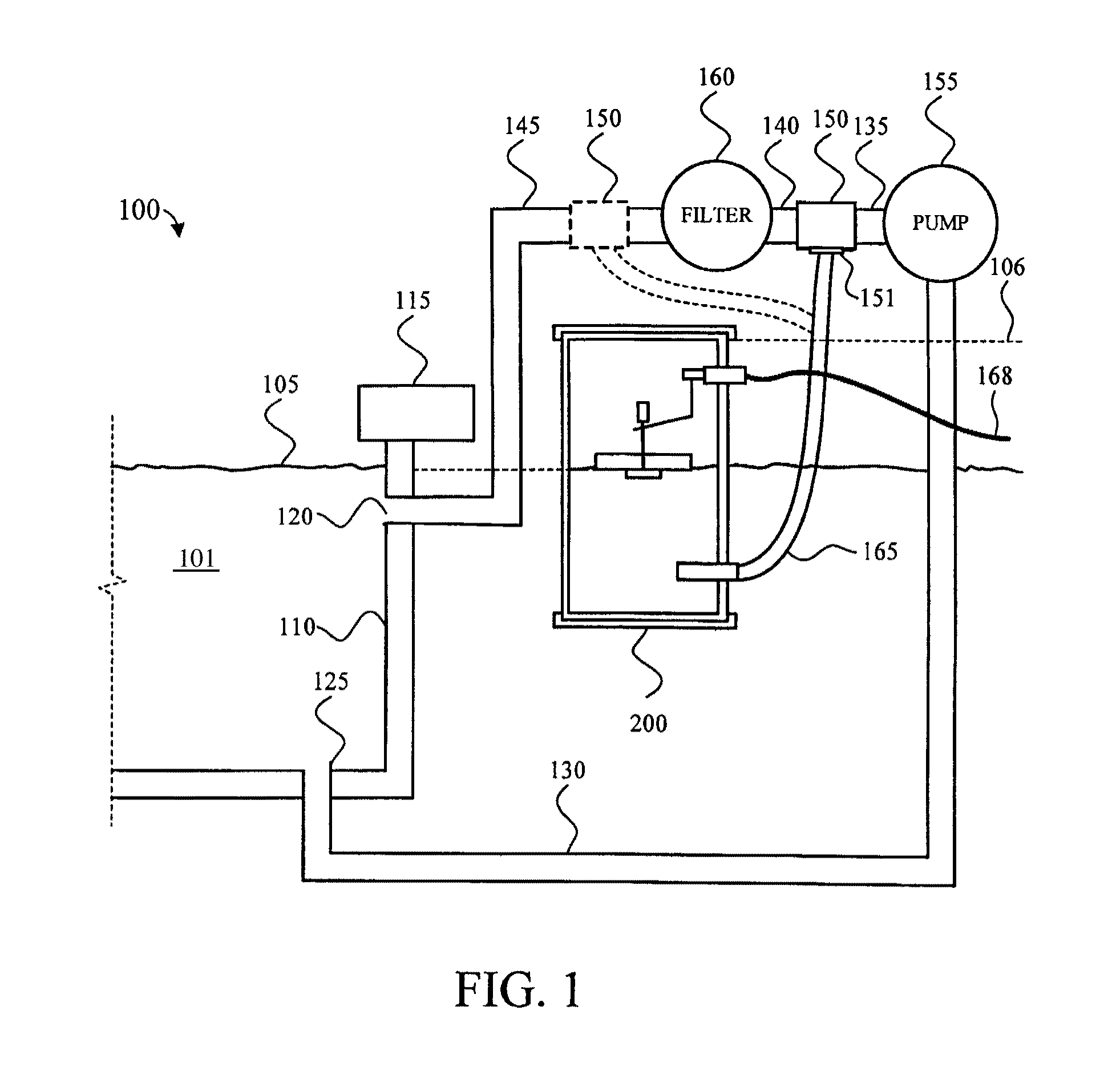
[0021]Referring now to FIG. 1, a schematic diagram of an in-ground swimming pool system 100 coupled to an automatic water leveler 200 in accordance with a preferred embodiment of the present invention is depicted. As shown in FIG. 1, pool system 100 comprises a pool structure 110, filled with water 101 wherein the top surface of water 101 is at water level 105; a pool deck 115; at least one pool outlet 125; at least one pool inlet 120; a plurality of water circulations pipes 130, 135, 140, and 145; a pump 155; and a filter 160.

[0022]With the notable exception of automatic water leveler 200 and its associated piping elements, pool system 100 is a fairly standard installation and pool systems of this type are well known to those skilled in the art. The various components of pool system 100 are used to provide a circulating water flow within pool structure 110. As shown in FIG. 1, automatic water leveler 200 is configured to be installable at several different locations on pool system ...


PUM


Abstract

An apparatus for automatically maintaining the water level of a body of water, such as a pool, is described herein. The present invention comprises a float body contained within a float housing chamber and selectively coupled to a float valve, a ball check valve employed as a means for isolating the pressurized water in the circulation system of a body of water from the water in the float chamber and, after pump operation has ceased, allowing the passage of supply water from the float chamber of the apparatus of the circulation system of a body of water. Flexible conduits or tubing may be provided for ease of installation. Furthermore, the present invention is intended to be conveniently located near the equipment of the circulation system for the body of water.

Description

RELATED APPLICATIONS[0001]This non-provisional patent application claims priority based on the filing date of U.S. Provisional Patent Application Ser. No. 61 / 099,669, which application was filed on Sep. 24, 2008, and which application is incorporated herein by reference.BACKGROUND OF THE INVENTION[0002]1. Technical Field[0003]The present invention relates generally to the field of in-ground bodies of water and more specifically relates to an apparatus for maintaining the desired level of water in a swimming pool, spa, or the like.[0004]2. Background Art[0005]Automatic water levelers of varying size, functionality, and complexity have been devised to maintain the water level of a spa, pool, or other similar types of in-ground bodies of water. Generally, automatic water levelers can be divided into two groups; water levelers that are positioned at the side of the body of water and in close proximity to the body of water, and pump-side water levelers. Pump-side water levelers typically...

Claims


Application Information

Patent Timeline
Patent Type & Authority Patents(United States)
IPC IPC(8): E04H4/12F16K31/18
CPCE04H4/12Y10T137/2795Y10T137/7439Y10T137/0402Y10T137/742Y10T137/7904Y10T137/7468
Inventor LARSEN, DAVID
Owner LARSEN DAVID
Why Eureka
Try Eureka