Electronic device, wiring board, and method of shielding noise
a technology of electronic devices and wiring boards, applied in the direction of cross-talk/noise/interference reduction, electrical apparatus contruction details, non-printed electric components of printed circuits, etc., can solve the problems of inadequate countermeasures and need to consider leakage of noise from gaps, so as to prevent the leakage of noise propagating
- Summary
- Abstract
- Description
- Claims
- Application Information
AI Technical Summary
Benefits of technology
Problems solved by technology
Method used
Image
Examples
first embodiment
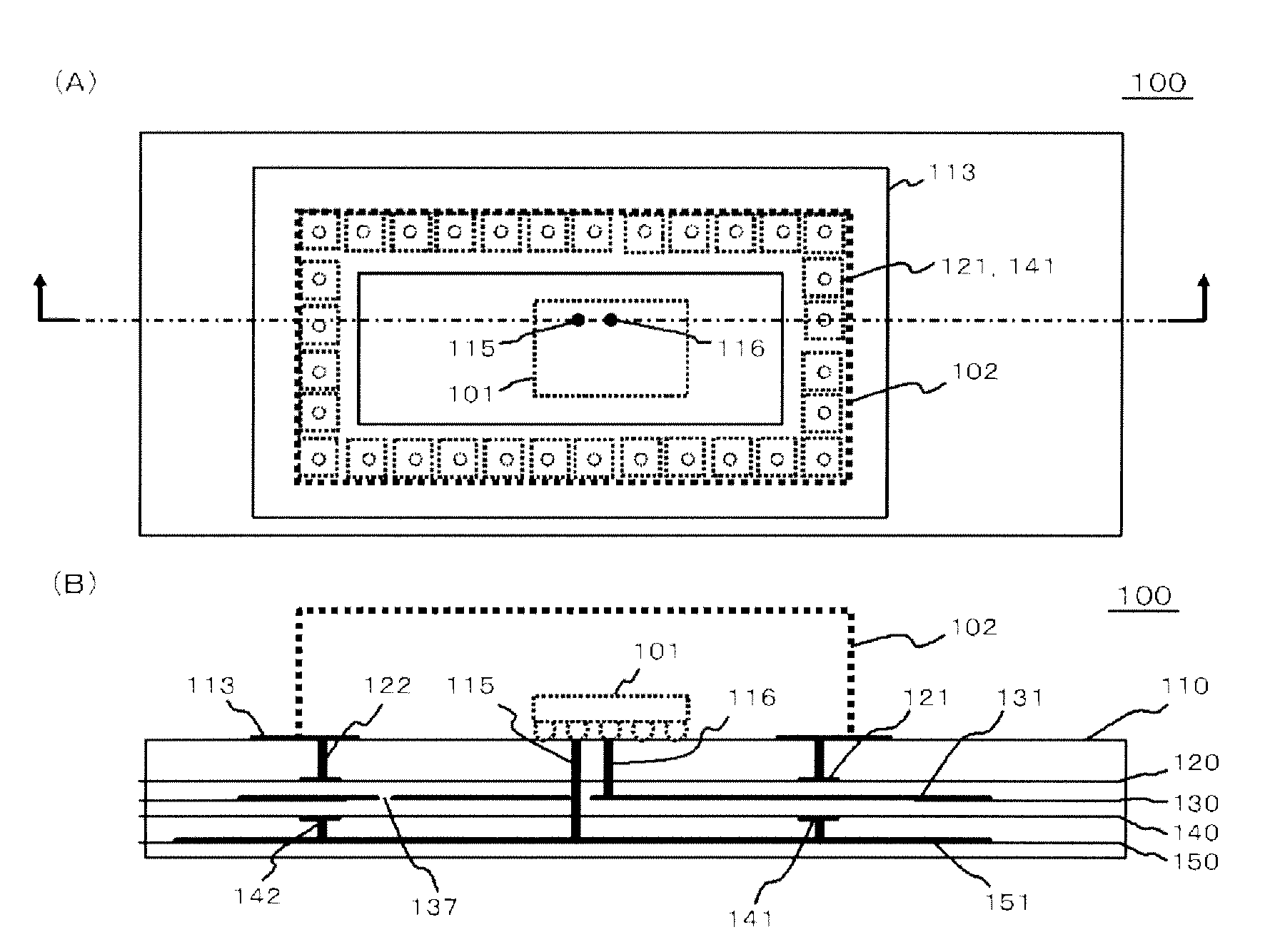
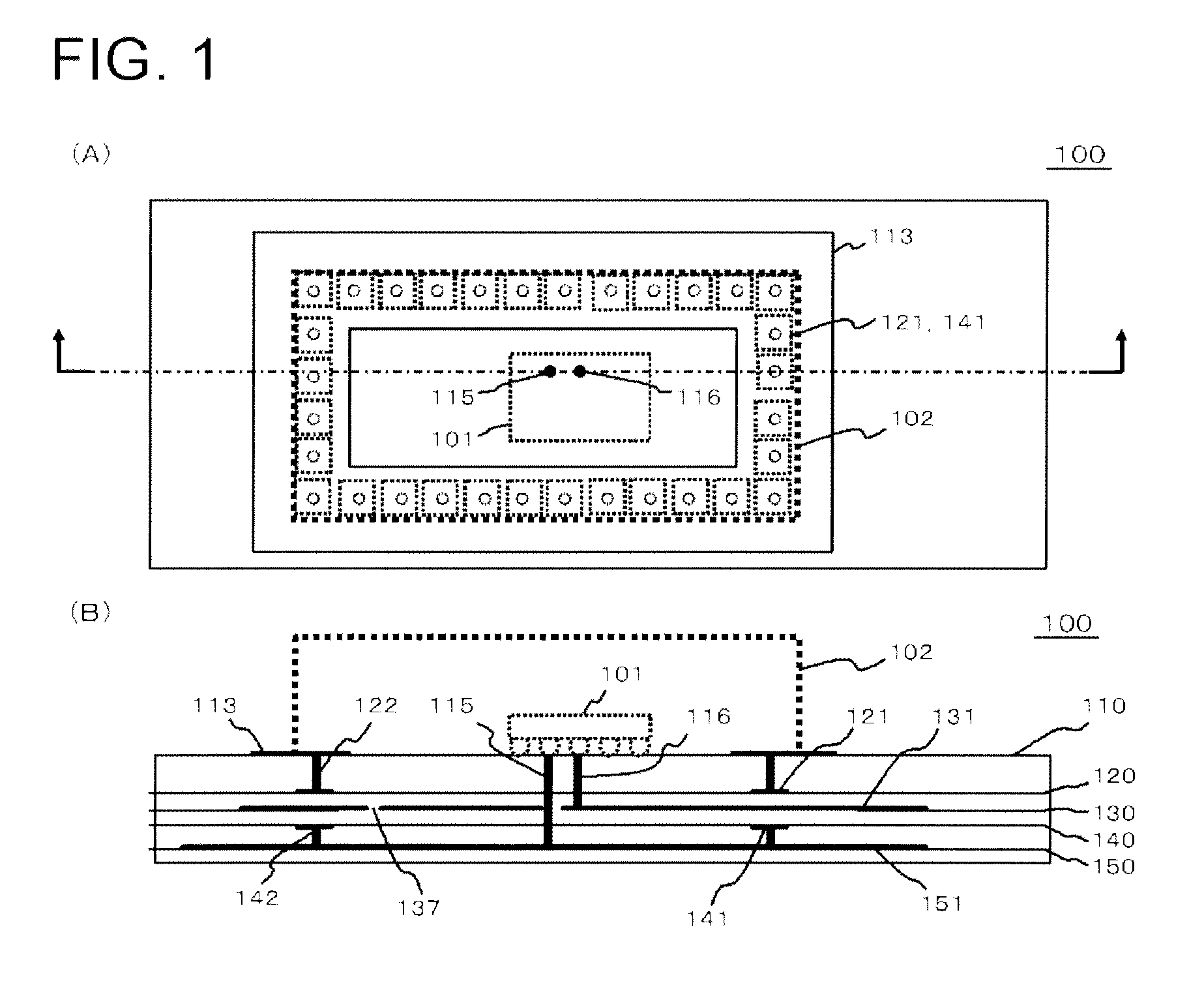
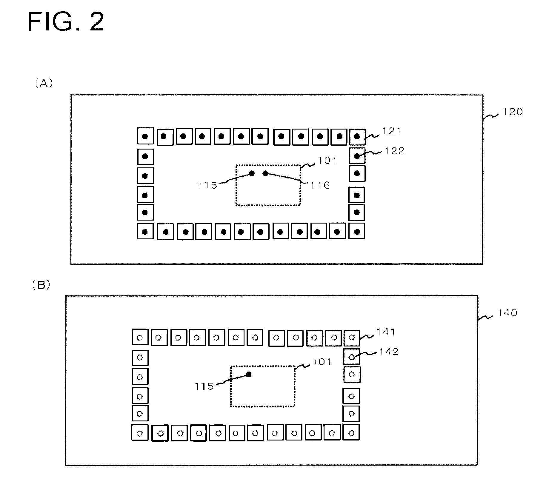
[0034]FIG. 1 represents a top view and a cross-sectional view of a wiring board 100 according to a first embodiment of the present invention. Described in more detail, FIG. 1(A) is a top view of the wiring board 100, and FIG. 1(B) is a cross-sectional view of the wiring board 100 that is taken along a cross-section line represented in FIG. 1(A). The wiring board 100 is a multi-layer board that includes at least an A layer 110, a B layer 120, a C layer 130, a D layer 140, and an E layer 150 facing one another. In addition, the wiring board 100 may further include a layer other than the above-described five layers. For example, a dielectric layer may be located between the layers. Furthermore, the wiring board 100 may further include a hole, a via, or the like that is not shown in the diagrams in a range not contradicting the configuration of the present invention. In addition, in the above-described five layers, signal lines may be arranged in a range not contradicting the configurat...
second embodiment
[0061]FIG. 6 represents a top view and a cross-sectional view of an electronic device 200 according to a second embodiment of the present invention. Described in more detail, FIG. 6(A) is a top view of the electronic device 200, and FIG. 6(B) is a cross-sectional view of an electronic device 200 that is taken along a cross-section line represented in FIG. 6(A). The electronic device 200 is a multi-layer board that includes at least an A layer 210, a B layer 220, a C layer 230, a D layer 240, an E layer 250, and an F layer 260, and a G layer 270 facing one another. In addition, the electronic device 200 may further include a layer other than the above-described seven layers. For example, a dielectric layer may be located between the layers. Furthermore, the electronic device 200 may further include a hole, a via, or the like that is not shown in the diagrams in a range not contradicting the configuration of the present invention. In addition, in the above-described seven layers, sign...
third embodiment
[0103]FIG. 16 represents a top view and a cross-sectional view of an electronic device 200 according to a third embodiment of the present invention. Described in more detail, FIG. 16(A) is a top view of the electronic device 200, and FIG. 16(B) is a cross-sectional view of the electronic device 200 that is taken along a cross-section line represented in FIG. 16(A). The electronic device 200 of this embodiment has a configuration that is acquired by adding an H layer 280 to the electronic device 200 described in the second embodiment. The constituent elements included in the A layer 210, the B layer 220, the C layer 230, the D layer 240, the E layer 250, the F layer 260, and the G layer 270 are similar to those of the second embodiment, and the detailed description thereof will not be presented.
[0104]FIG. 17 is a diagram that illustrates the H layer 280 of the electronic device 200. The H layer 280 (third layer) is located between the A layer 210 and the B layer 220 and faces the G l...
PUM
 Abstract
Description
Claims
Application Information
 - R&D
- Intellectual Property
- Life Sciences
- Materials
- Tech Scout
- Unparalleled Data Quality
- Higher Quality Content
- 60% Fewer Hallucinations
Browse by: Latest US Patents, China's latest patents, Technical Efficacy Thesaurus, Application Domain, Technology Topic, Popular Technical Reports.
© 2025 PatSnap. All rights reserved.Legal|Privacy policy|Modern Slavery Act Transparency Statement|Sitemap|About US| Contact US: help@patsnap.com


