Hydraulic actuation of a downhole tool assembly

a technology of hydraulic actuation and downhole tool, which is applied in the direction of well/borehole valve arrangement, borehole/well accessories, drilling machines and methods, etc., can solve the problems of increasing differential pressure, not typically allowing repeated actuation and deactuation of downhole tools, and reducing operational uncertainties, so as to reduce the erosion of internal tool components and the pressure drop through the tool during use. , the effect of reducing operational uncertainties

Active Publication Date: 2014-10-21
SMITH INT INC
View PDF64 Cites 4 Cited by
  • Summary
  • Abstract
  • Description
  • Claims
  • Application Information

AI Technical Summary

Benefits of technology

[0009]Exemplary embodiments of the present invention advantageously provide several technical advantages. For example, the present invention enables a downhole tool to be selectively and repeatedly actuated and deactuated substantially any number of times without breaking the drill string and / or or tripping the tool out of the borehole. The invention further obviates the need for physical actuation and deactuation (e.g., including the use of darts, ball drops, and the like).
[0010]Moreover, embodiments of the invention advantageously allow a downhole tool to be in a deactuated state while providing full drilling fluid flow through the tool. In certain exemplary embodiments of the invention unobstructed flow may be advantageously provided through a central bore. This tends to minimize both the pressure drop through the tool and erosion of internal tool components during use. Being purely mechanical (not requiring the use of any electronic monitoring or control), downhole tool assemblies in accordance with the present invention also tend to be highly reliable and serviceable.
[0011]Certain embodiments of the invention may also be configured to provide an indication to the surface of the tool actuation / deactuation status, for example, a pressure drop indicating tool actuation. Such an indication tends to advantageously reduce operational uncertainties. Various embodiment of the invention also allow the drilling fluid flow rate to be repeatedly cycled between high and low flow rates without actuating or deactuating the downhole tool. This feature of the invention may also enhance operational certainty as it tends to eliminate inadvertent actuation and deactuation.

Problems solved by technology

While commercially serviceable, such wireline actuation and deactuation is both expensive and time-consuming in that it requires concurrent use of wireline or slickline assemblies.
Engagement of the ball with the seat typically causes an increase in differential pressure which in turn actuates the downhole tool.
While such sheer pin and ball drop mechanisms are also commercially serviceable, they are generally one-time or one-cycle mechanisms and do not typically allow for repeated actuation and deactuation of a downhole tool.
However, these actuation systems tend to be highly complex and expensive and can be severely limited by the reliability and accuracy of MWD, telemetry, and other electronically controllable systems deployed in the borehole.
As a result, there are many applications ins which their use tends to be undesirable.

Method used


Image

  • Hydraulic actuation of a downhole tool assembly
  • Hydraulic actuation of a downhole tool assembly
  • Hydraulic actuation of a downhole tool assembly

Examples


Embodiment Construction

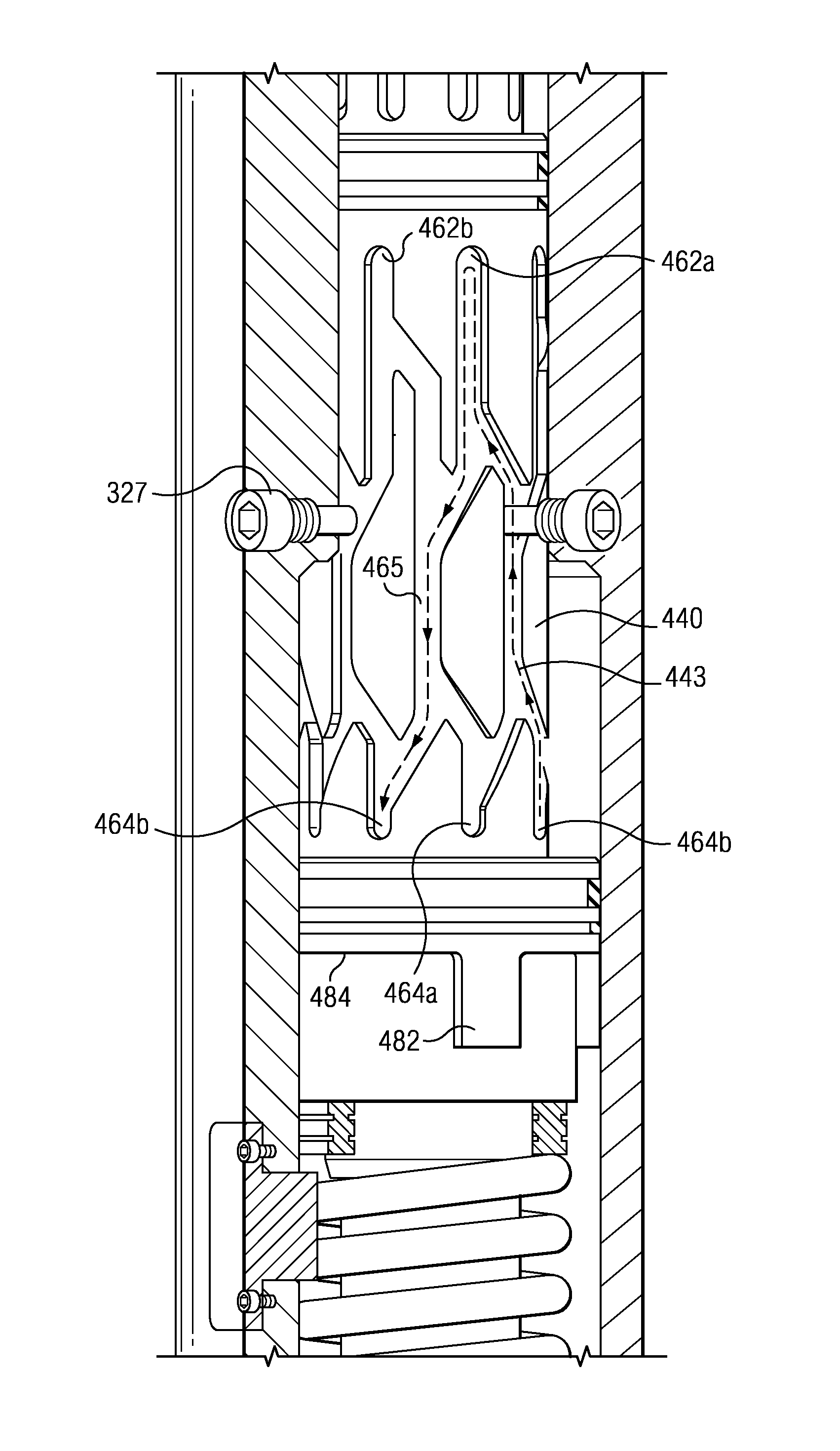
[0034]Referring to FIGS. 1 through 17, exemplary embodiments of the present invention are depicted. With respect to FIGS. 1 through 17, it will be understood that features or aspects of the embodiments illustrated may be shown from various views. Where such features or aspects are common to particular views, they are labeled using the same reference numeral. Thus, a feature or aspect labeled with a particular reference numeral on one view in FIGS. 1 through 17 may be described herein with respect to that reference numeral shown on other views.

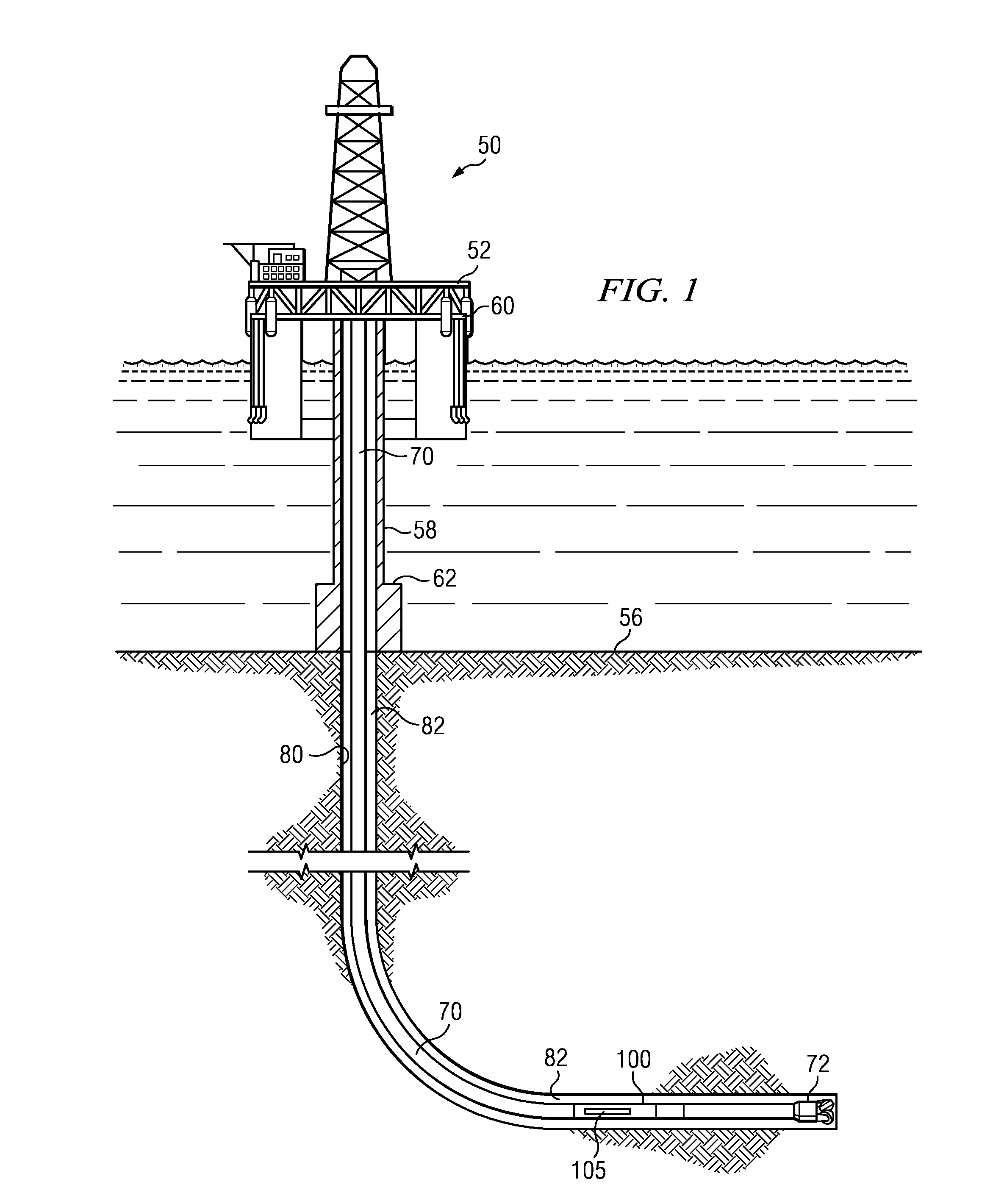
[0035]FIG. 1 depicts an exemplary offshore drilling assembly, generally denoted 50, suitable for use with downhole tool embodiments in accordance with the present invention. In FIG. 1 a semisubmersible drilling platform 52 is positioned over an oil or gas formation (not shown) disposed below the sea floor 56. A subsea conduit 58 extends from deck 60 of platform 52 to a wellhead installation 62. The platform may include a derrick and a hoisting ...


PUM


Abstract

A downhole tool assembly is configured for repeated and selective hydraulic actuation and deactuation. A piston assembly is configured to reciprocate axially in a downhole tool body. The piston assembly reciprocates between a first axial position and second and third axial positions that axially oppose the first position. The downhole tool is actuated when the piston assembly is in the third axial position and deactuated when the piston assembly is in either of the first or second axial positions. A spring member biases the piston assembly towards the first axial position while drilling fluid pressure in the tool body urges the piston assembly towards the second and third axial positions. Downhole tool actuation and deactuation may be controlled from the surface, for example, via cycling the drilling fluid flow rate.

Description

RELATED APPLICATIONS[0001]This application claims the benefit of U.S. Provisional Application Ser. No. 61 / 347,318 entitled “Reamer on Demand Actuator”, filed May 21, 2010.FIELD OF THE INVENTION[0002]The present invention relates generally to a hydraulic actuation mechanism for use in downhole tools. More specifically, the invention relates to a hydraulic actuation assembly enabling a substantially unlimited number of actuation and deactuation cycles of a downhole tool, such as a reamer, without having to break or trip a tool string.BACKGROUND OF THE INVENTION[0003]Downhole drilling operations commonly require a downhole tool to be actuated after the tool has been deployed in the borehole. For example, underreamers are commonly tripped into the borehole in a collapsed state (i.e., with the cutting structures retracted into the underreamer tool body). At some predetermined depth, the underreamer is actuated such that the cutting structures expand radially outward from the tool body. H...

Claims


Application Information

Patent Timeline
Patent Type & Authority Patents(United States)
IPC IPC(8): E21B10/32E21B34/00E21B23/00
CPCE21B23/006E21B10/32E21B7/28E21B34/06
Inventor WU, JIANHU, JIANBINGTERRACINA, DWAYNE PRAY, TOMMY G
Owner SMITH INT INC
Why Eureka
Try Eureka