
Amplifier with gain circuit coupeld to primary coil of transformer

a transformer and gain circuit technology, applied in the field of low noise amplifiers, can solve the problems of generating erroneous demodulation of demodulators, and achieve the effects of reducing noise, reducing noise, and small circuit area

Active Publication Date: 2014-10-14
REALTEK SEMICON CORP
View PDF3 Cites 7 Cited by
  • Summary
  • Abstract
  • Description
  • Claims
  • Application Information

AI Technical Summary

Benefits of technology

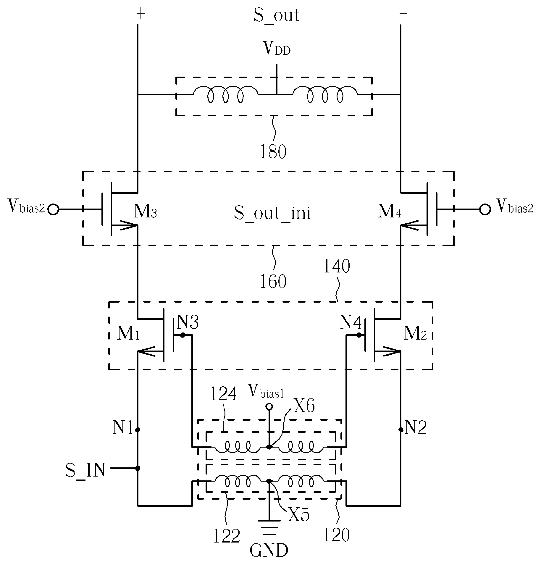
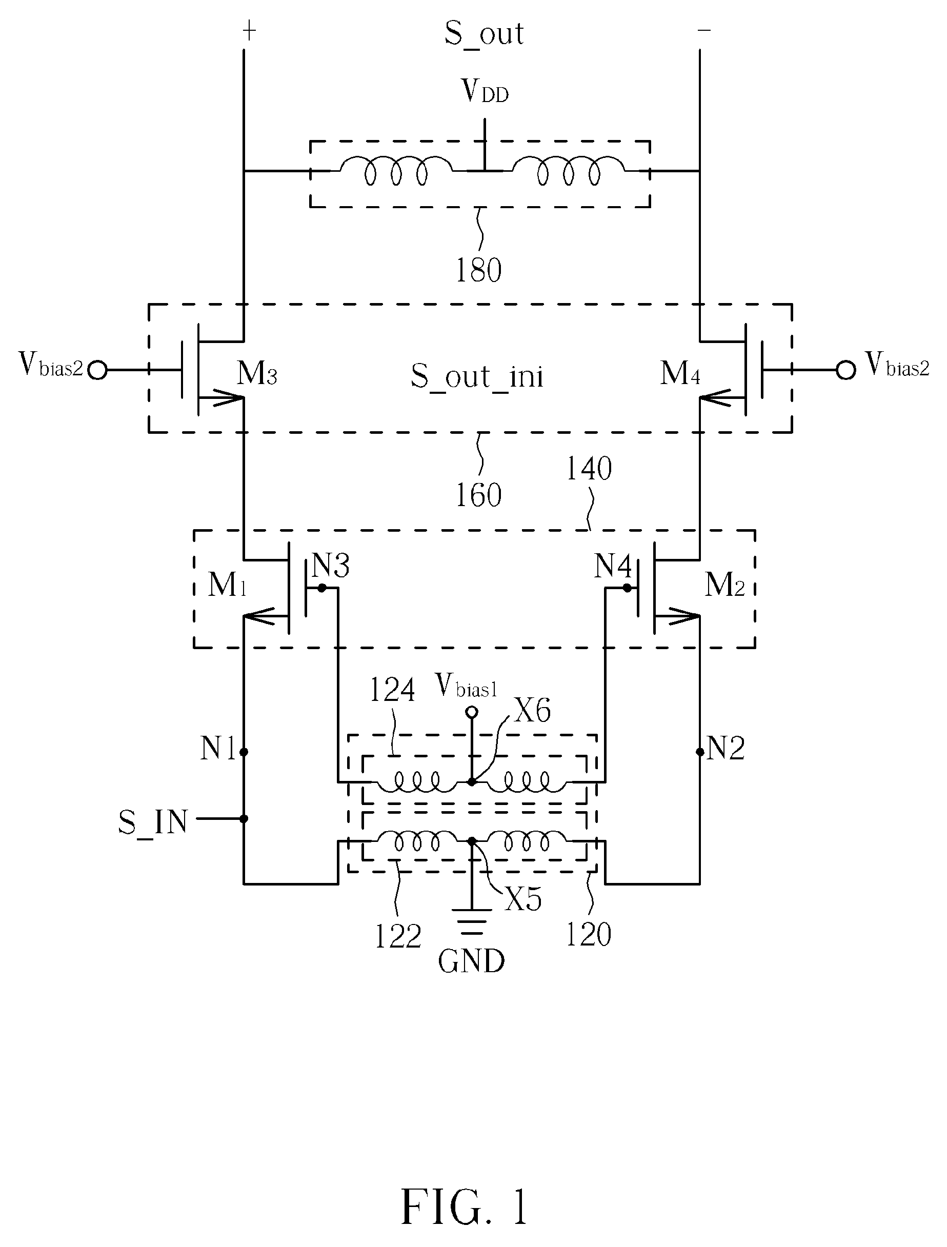
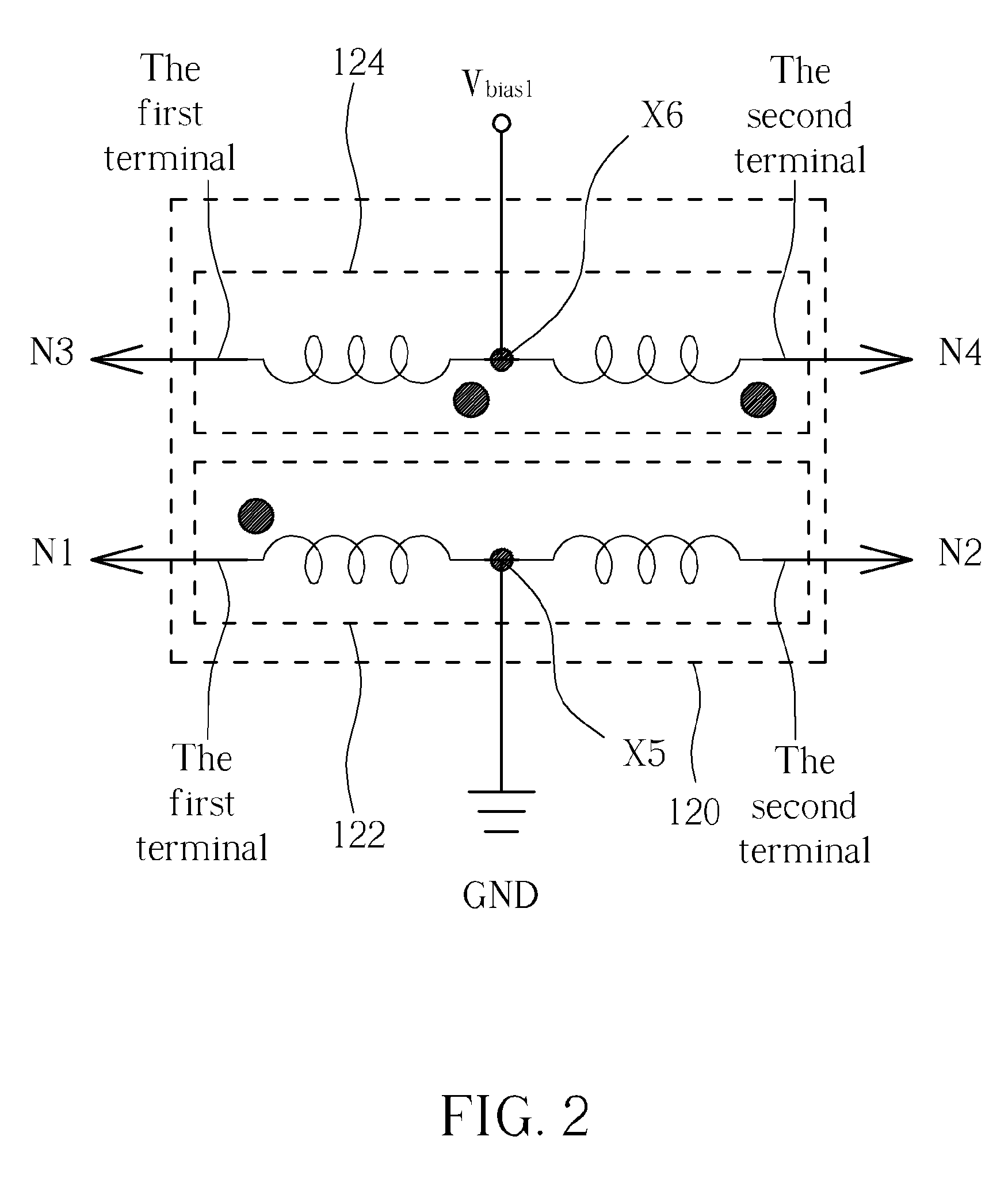
[0005]Therefore, one purpose of the present invention is to provide a low noise amplifier with a smaller circuit area, which is achieved by integrating part of the elements in the amplifier. Additionally, another purpose of the present invention is to lower the noise introduced by the amplifier itself by employing the transformer at the input terminal, thereby achieving good noise suppression effect.

Problems solved by technology

The design of the low noise amplifier requires many considerations, especially the noise from the amplifier itself.
If too much noise is introduced to the wireless signal in the process of amplifying the wireless signal, the demodulator would generate an erroneous demodulation result.

Method used


Image

  • Amplifier with gain circuit coupeld to primary coil of transformer
  • Amplifier with gain circuit coupeld to primary coil of transformer
  • Amplifier with gain circuit coupeld to primary coil of transformer

Examples


Embodiment Construction

[0012]Certain terms are used throughout the following description and claims, which refer to particular components. As one skilled in the art will appreciate, electronic equipment manufacturers may refer to a component by different names. This document does not intend to distinguish between components that differ in name but not in function. In the following description and in the claims, the terms “include” and “comprise” are used in an open-ended fashion, and thus should be interpreted to mean “include, but not limited to . . . ”. Also, the term “couple” is intended to mean either an indirect or direct electrical connection. Accordingly, if one device is coupled to another device, that connection may be through a direct electrical connection, or through an indirect electrical connection via other devices and connections.

[0013]Please refer to FIG. 1, which is a circuit diagram illustrating an embodiment of the amplifier of the present invention. As shown in FIG. 1, the amplifier 10...


PUM


Abstract

An amplifier includes a transformer and a first stage gain circuit. The transformer includes a primary coil and a secondary coil. The primary coil is utilized for receiving an input signal. The first stage gain circuit has a first input port, which is coupled to the primary coil. The first stage gain circuit is utilized for gaining the input signal so as to generate a first output.

Description

BACKGROUND OF THE INVENTION[0001]1. Field of the Invention[0002]The present invention relates to the field of wireless communication, and more particularly, to a low noise amplifier employed in a receiver.[0003]2. Description of the Prior Art[0004]In the wireless communication system, the receiver applies a gain to the wireless signal received by the antenna through the low noise amplifier (LNA), and accordingly provides the amplified wireless signal to the following demodulator for demodulation. The design of the low noise amplifier requires many considerations, especially the noise from the amplifier itself. If too much noise is introduced to the wireless signal in the process of amplifying the wireless signal, the demodulator would generate an erroneous demodulation result. That is, the low noise amplifier should be properly designed to have the noise figure as low as possible to ensure the correctness of the data transmitted. Besides, due to the trend of the minimization of the ...

Claims


Application Information

Patent Timeline
Patent Type & Authority Patents(United States)
IPC IPC(8): H03F3/45
CPCH03F3/45H03F1/223H03F3/195H03F3/26H03F3/45179H03F2200/294H03F2203/45394H03F2203/45621H03F2203/45638
Inventor CHEN, HSIEN-KUCHANG, CHIA-JUNCHAN, KA-UNLIN, YING-HSI
Owner REALTEK SEMICON CORP
Learn More