Mouse pen and photoelectric control switch thereof

a technology of photoelectric control switch and mouse pen, which is applied in the field of mouse pen and photoelectric control switch, can solve the problems of increasing user's use-cost, reducing the useful life of the pen, and reducing the sensitivity of the pen, so as to facilitate assembly, reduce the size of the pen, and simplify the structure

Inactive Publication Date: 2014-09-30
SHENZHEN YIBAO TECH
View PDF25 Cites 0 Cited by
  • Summary
  • Abstract
  • Description
  • Claims
  • Application Information

AI Technical Summary

Benefits of technology

[0006]A technical problem to be solved in the present invention is to provide a photoelectric control switch, so as to effectively improve useful life period of the photoelectric control switch.
[0008]One more technical problem to be solved in the present invention is to provide a mouse pen, which can reduce outer diameter of a bottom end of a penholder so as to improve grasping comfort.
[0020]The advantages of the present invention are that: since the photoelectric control switch is constructed via the optical coupling sensor being engaged with the control rod which is equipped with a reflection layer, light emitting from the optical coupling sensor is reflected by the reflection layer, when the control rod is set on the on-position, light emitting from the light emitter of the optical coupling sensor is reflected by the reflection layer and then is received by the light receiver, while the control rod is set on the off-position, the light receiver of the optical coupling sensor can not receive the light emitting from the lighter emitter and being reflected by the reflection cap, thereby, the photoelectric control switch implements non-contact on / off controlling with an optical coupling sensor, and accordingly effectively prolongs a useful life period of the control switch; moreover, the optical coupling sensor responses to control operations rapidly and sensitively.
[0021]Via the transmit-receive integrative chip of which the laser-generating chip and the image receiver are integratedly arranged, the components to be assembled in the bottom of the penholder can be reduced, the penholder has a simpler structure, not only facilitates assembling, but further reduces the bottom size thereof so as to raise the grasping comfort.
[0022]Moreover, via using ball pen core or ink pen core in our usual work and life as the penpoint of mouse pen, users can conveniently replace the penpoint if desired, and can also use the mouse pen as general ball pen or ink pen; the penholder is equipped with the wireless transmitter therein, and is detachably equipped with the wireless receiver in top end thereof for conveniently taking with the wireless receiver; in use of the mouse pen, the wireless receiver is detached and inserted into the computer, so that the mouse pen can be conveniently used whenever and wherever; the laser-pointer module being set in the penholder enables the mouse pen used as a laser pointer, and thus expands the functions of mouse pen.

Problems solved by technology

Such mechanical control switch is contact-type, time difference certainly exists between switch-on and switch-off, thus it cannot respond rapidly and in time; and the contact part thereof for switch-on will generate fatigue deformation and wear, the sensitivity thereof will be gradually degraded, and thus the useful life period thereof will be limited.
Generally, the actual life period of the mechanical control switch just can be clicked by tens of or at most millions of times, often it is the shortest-lifetime component among all components of the mouse device, and consequently increases the use-cost of user's.
Because the mouse pen needs respectively set LED light and image receiver, assembling is relatively miscellaneous, outer diameter of the penholder bottom is difficultly reduced, and the big penholder reduces grasping comfort.
However, for such installation structure of the existing penpoint, when desired to replace the penpoint, it is necessary to detach the penpoint together with the pen head, and to reassemble pen head back after the penpoint is replaced, and operations are miscellaneous.
Furthermore, the penpoint of existing mouse pen is specially designed and manufactured, when the penpoint is damaged, the user cannot replace it himself, and yet cannot choose to replace it according to his desire.

Method used


Image

  • Mouse pen and photoelectric control switch thereof
  • Mouse pen and photoelectric control switch thereof
  • Mouse pen and photoelectric control switch thereof

Examples


second embodiment

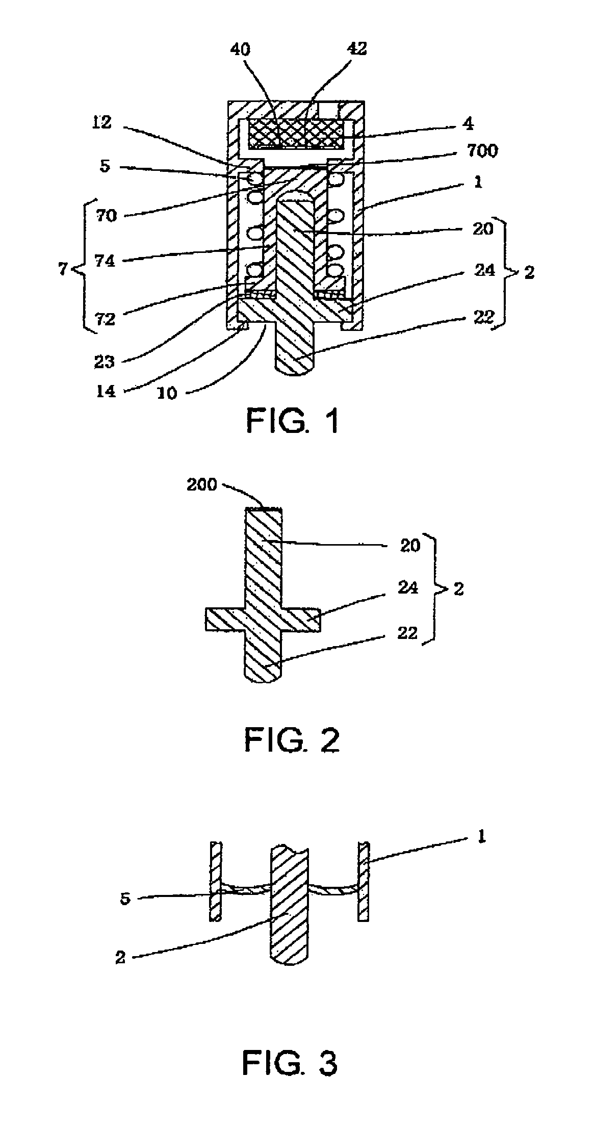
[0045]As shown in FIG. 2 in accordance with the second embodiment, an outer surface of the second end 22 of the control rod 2 is equipped with a reflection layer 200 as the reflection element to replace the reflection cap 7, which performs the same function of reflecting light emitting from the light emitter 40 of the optical coupling sensor 4. Herein, the elastic element 5 is directly worn on the control rod 2.

third embodiment

[0046]As shown in FIG. 3 in accordance with the third embodiment, the elastic element 5 can also take the form of elastic sheet with a proper elasticity, of which one end is fixed relative to the control rod 2, and the other end is fixed relative to the shell 1. In the same way, when the control rod 2 moves towards the optical coupling sensor 4, the elastic element 5 will generate elastic bending so as to provide an elastic restoring force to the control rod 2 once the external force applied to the second end of the control rod 2 is removed.

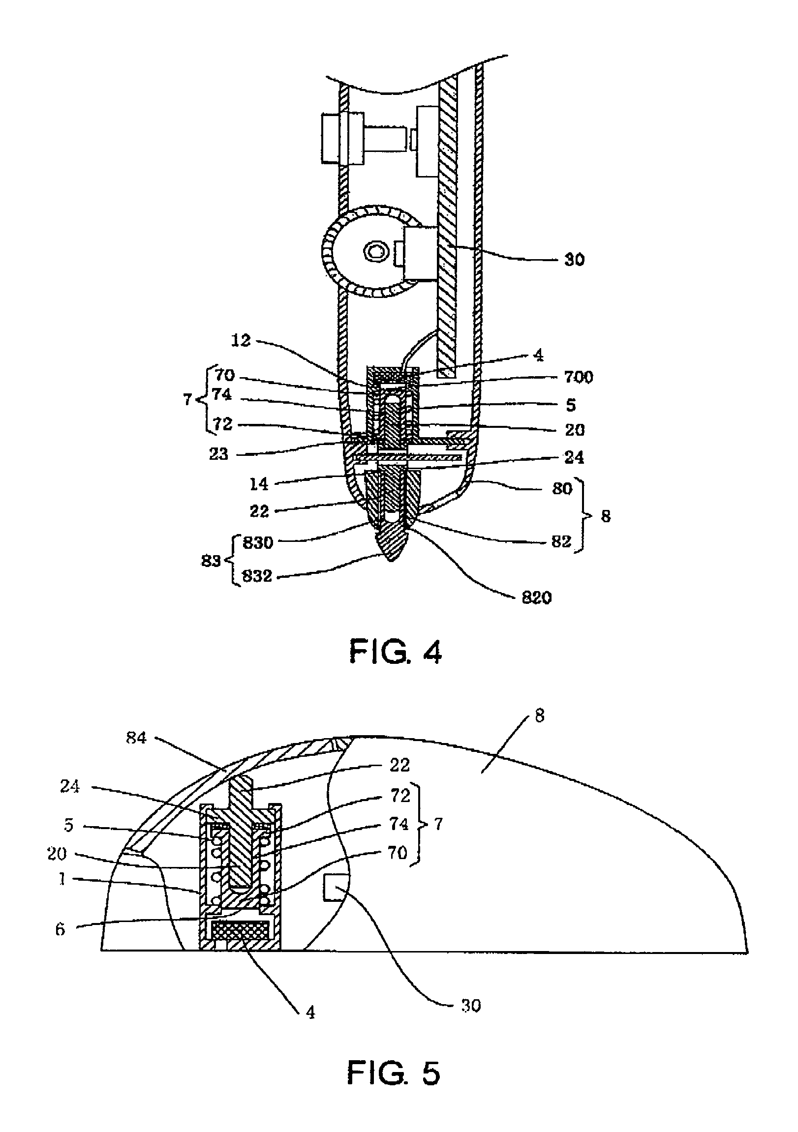
[0047]The above photoelectric control switch can be applied to various mouse devices, when such photoelectric control switch described above is arranged in housing 8 of the mouse device. All kinds of traditional function control switch of mouse device, such as: left button, right button, middle button, and etc., can be performed by using the photoelectric control switch of the present invention. The photoelectric control switch of the present inv...

first embodiment

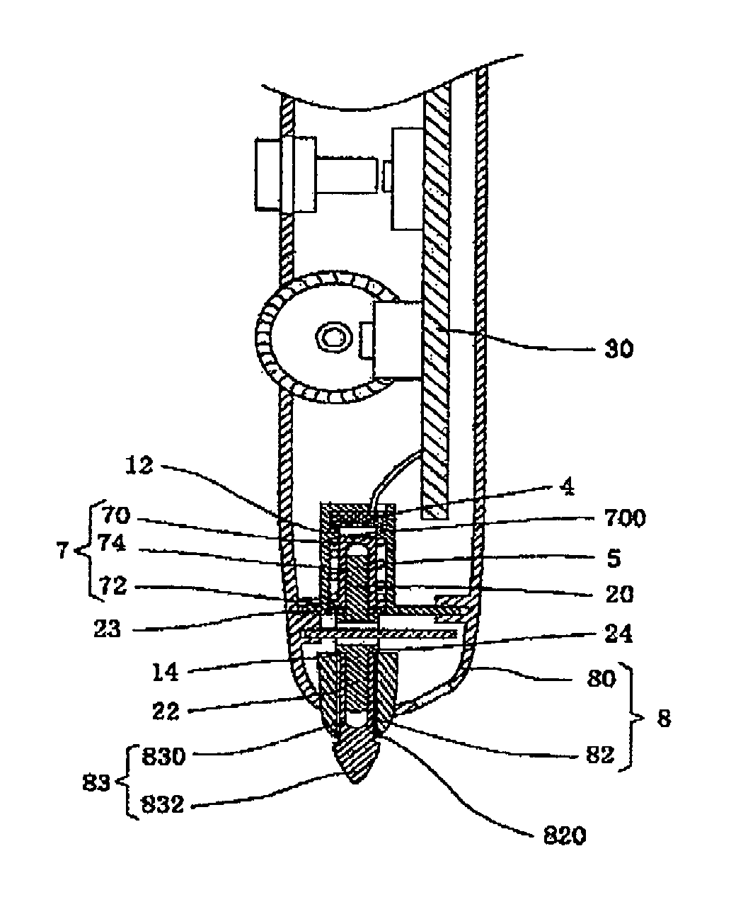
[0050]On the other hand, the present invention also provides a mouse pen, as shown in FIG. 6 in accordance with the mouse pen, the mouse pen comprises the penholder 80, the penpoint 83 being inserted in the bottom end of the penholder 80, control circuit component set inside the penholder 80, optical component 6, and power source 90.

[0051]The penholder 80 is hollow for accommodating the control circuit component, optical component 6, and so on, and defines the insert hole in the bottom end thereof so as to penetrate the penpoint 83. At a top side of the penholder 80 is further set an elastic pen clip 800, a bottom side of the penholder 80 protrudes to form an embossment part 81 for receiving the optical component 6 therein, and a bottom surface of the embossment part 81 defines a light hole 801, and the optical component 6 is set aligned to the bottom end of the penpoint 83.

[0052]The control circuit component comprises a control circuit board 30 disposed inside the penholder 80, the...


PUM


Abstract

A mouse pen and a photoelectric control switch thereof are provided, the photoelectric control switch includes a control rod in a shell moving between on-position and off-position, an optical coupling sensor comprising a light emitter and light receiver disposed on an extension line of the control rod, and an elastic element for resetting the control rod. The control rod includes a first end near the optical coupling sensor and equipped with a reflection element, and a second end for driving the control rod towards the optical coupling sensor which protrudes an orifice of the shell; at the on-position, light emitting from the light emitter is received by the light receiver after being reflected by the reflection element, while at the off-position, light cannot be received. The photoelectric control switch implements non-contact on / off controlling with the optical coupling sensor and the control rod, responses sensitively, and has longer lifetime.

Description

CROSS REFERENCE TO RELATED APPLICATIONS[0001]The present application is a 35 U.S.C. §371 National Phase conversion of International (PCT) Patent Application No. PCT / CN2010 / 077895, filed on Oct. 19, 2010, the disclosure of which is incorporated by reference herein. The PCT International Patent Application was published in Chinese.FIELD OF THE INVENTION[0002]The present invention relates to a computer auxiliary input device, especially to a mouse pen and photoelectric control switch thereofBACKGROUND OF THE INVENTION[0003]In the existing mouse device such as mouse pen and traditional mouse, left button, right button, middle button and all control switch are mechanical control switch, such as microswitch or thin-film switch. Such mechanical control switch is contact-type, time difference certainly exists between switch-on and switch-off, thus it cannot respond rapidly and in time; and the contact part thereof for switch-on will generate fatigue deformation and wear, the sensitivity the...

Claims


Application Information

Patent Timeline
Patent Type & Authority Patents(United States)
IPC IPC(8): G09G5/08G06F3/0354
CPCG06F3/03542G06F3/03545
Inventor TUAN, HSI-CHINGTUAN, CHAO-YANG
Owner SHENZHEN YIBAO TECH
Why Eureka
Try Eureka