
Composite component

a technology of composite components and components, applied in the field of composite components, can solve the problems of difficult to sufficiently reduce the difficulty of sufficiently reducing unnecessary interference occurring between the transmission signal and the reception signal, so as to reduce unnecessary interferen

Active Publication Date: 2014-09-30
MURATA MFG CO LTD
View PDF16 Cites 0 Cited by
  • Summary
  • Abstract
  • Description
  • Claims
  • Application Information

AI Technical Summary

Benefits of technology

[0006]Therefore, preferred embodiments of the present invention significantly reduce unnecessary interference occurring between various types of signals in a composite component in which a duplexer that separates various types of signals such as transmission and reception signals is mounted.
[0008]According to various preferred embodiments of the present invention, it is possible to significantly reduce unnecessary interference occurring between various types of signals in a composite component in which a duplexer that separates various types of signals is mounted.

Problems solved by technology

However, the antenna switch module described in Japanese Unexamined Patent Application Publication No. 2006-295530 has a problem in that it is difficult to sufficiently reduce unnecessary interference occurring between the transmission signal and the reception signal.
However, in the antenna switch module, since the area of the ground conductor is small, it is difficult to sufficiently reduce unnecessary interference occurring between the transmission signal and the reception signal.

Method used


Image

  • Composite component
  • Composite component
  • Composite component

Examples


Embodiment Construction

[0015]Hereinafter, a circuit module according to preferred embodiments of the present invention will be described with reference to drawings.

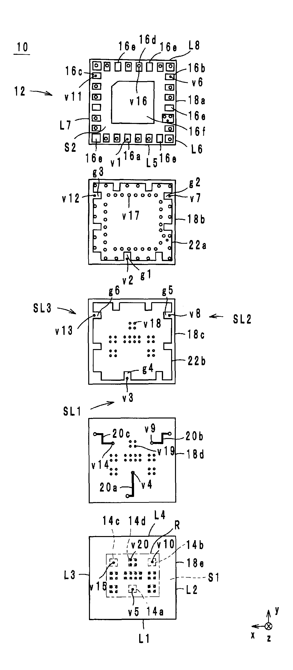
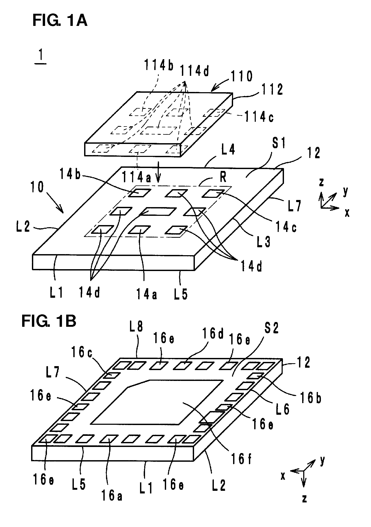
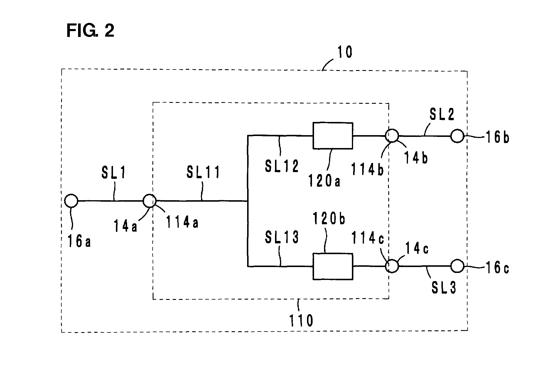
[0016]First, the configuration of the circuit module will be described with reference to drawings. FIGS. 1A and 1B are external appearance perspective views of a circuit module 1 according to a preferred embodiment of the present invention. FIG. 1A is a view when the circuit module 1 is viewed from above, and FIG. 1B is a view when the circuit module 1 is viewed from below. FIG. 2 is the circuit diagram of the circuit module 1. FIG. 3 is the exploded view of a circuit substrate 10 of the circuit module 1.

[0017]Hereinafter, the lamination direction of the circuit substrate 10 is defined as a z-axis direction. Directions in which individual sides of the circuit substrate 10 extend when the planar view of the circuit substrate 10 is seen from the z-axis direction are defined as an x-axis direction and a y-axis direction. In FIGS. 1A and 1B, it is ...


PUM


Abstract

A circuit substrate on which a duplexer is mounted includes a substrate body. First, second and third external electrodes are provided on a first main surface of the substrate body. Fourth, fifth and sixth external electrodes are provided on a second main surface of the substrate body. First, second and third signal paths connect the first, second and third external electrodes to the fourth, fifth and sixth external electrodes, respectively. First and second ground conductors are embedded in the substrate body, and overlap with a mounting area so as to contain the mounting area where the duplexer is mounted, in a planar view seen from the z-axis direction. The first, second and third signal paths extend from the inside of the mounting area to the outside of the mounting area between the first main surface and the second ground conductor.

Description

BACKGROUND OF THE INVENTION[0001]1. Field of the Invention[0002]The present invention relates to a composite component, and more specifically, relates to a composite component in which a duplexer is mounted.[0003]2. Description of the Related Art[0004]As a composite component of the related art, for example, an antenna switch module described in Japanese Unexamined Patent Application Publication No. 2006-295530 is known. In the corresponding antenna switch module, a transmission signal and a reception signal are separated in a plurality of communication methods received through an antenna. In addition, the separated transmission signal and reception signal are transmitted within a laminated dielectric. In such an antenna switch module, it is necessary to reduce unnecessary interference occurring between the transmission signal and the reception signal.[0005]However, the antenna switch module described in Japanese Unexamined Patent Application Publication No. 2006-295530 has a proble...

Claims


Application Information

Patent Timeline
Patent Type & Authority Patents(United States)
IPC IPC(8): H01P5/12H03H7/46H03H7/01H03H9/05H03H9/72H04B1/44
CPCH03H7/0138H03H9/725H03H7/463H04B1/44H03H9/0576
Inventor TAKEUCHI, MORIO
Owner MURATA MFG CO LTD
Learn More