
High-throughput printing of semiconductor precursor layer from microflake particles

a technology of microflake particles and precursor layers, applied in the field of semiconductor precursor layers, to achieve the effect of simplifying creation and ensuring efficiency

Inactive Publication Date: 2014-09-30
AERIS CAPITAL SUSTAINABLE IP
View PDF189 Cites 6 Cited by
  • Summary
  • Abstract
  • Description
  • Claims
  • Application Information

AI Technical Summary

Benefits of technology

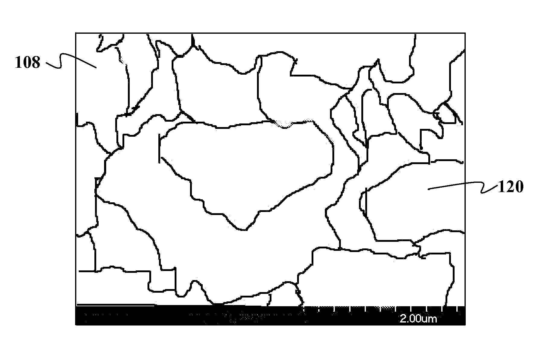
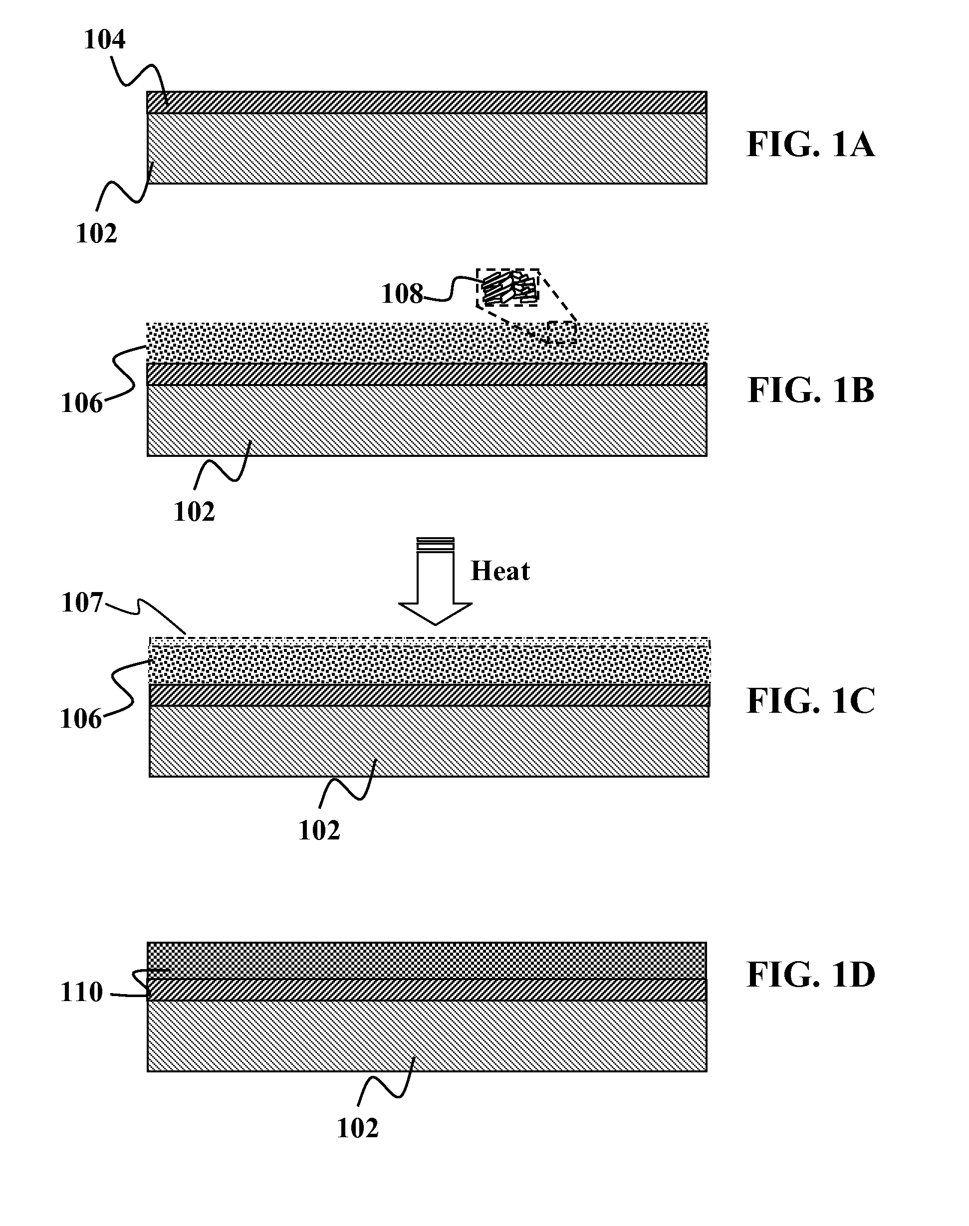
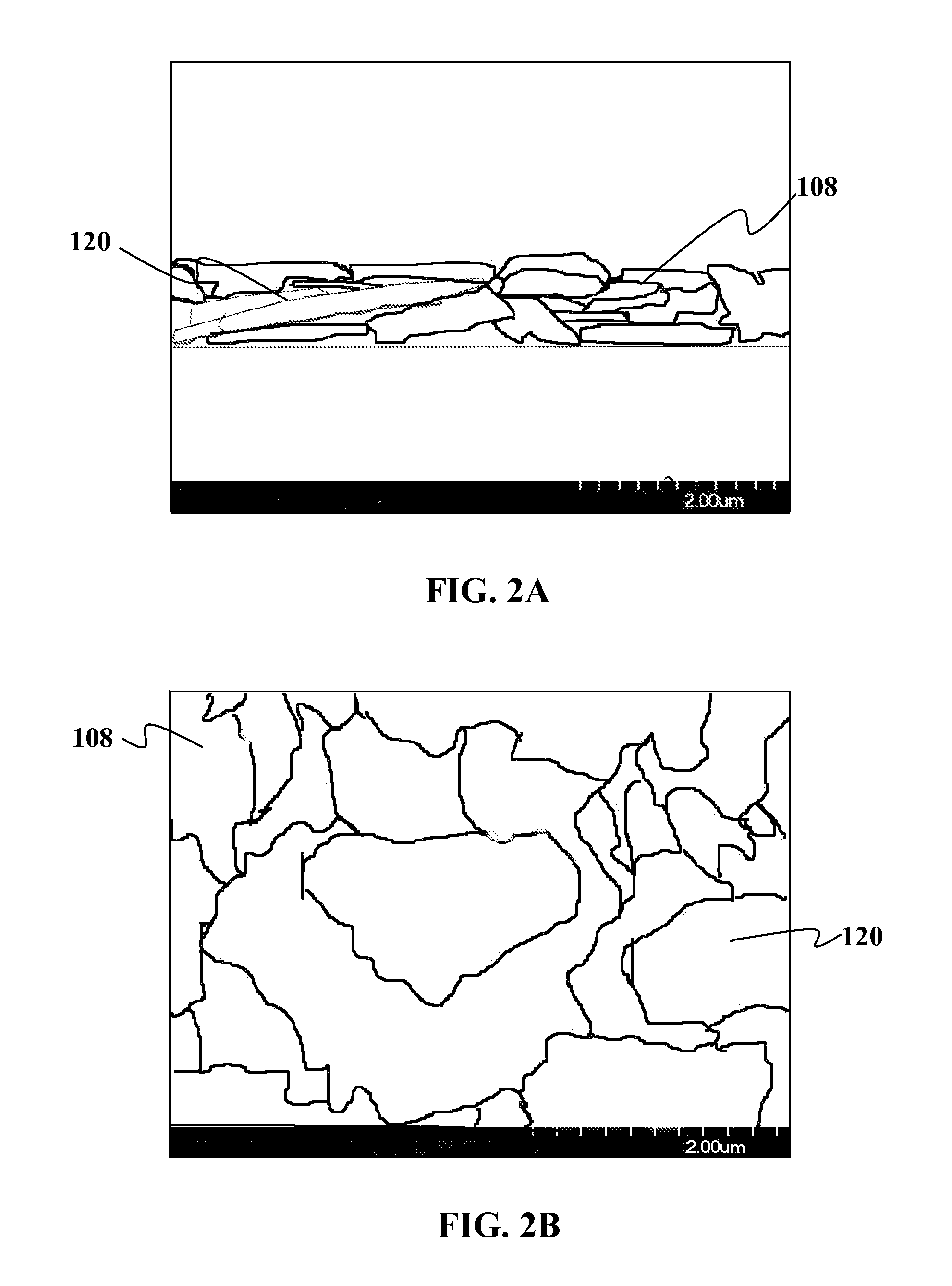
The patent describes a method for making microflakes that can be used in various applications such as inkjet printing. The microflakes have a planar shape that provides advantages over spherical nanoparticles, such as better surface area contact and faster annealing at lower temperatures. The planar shape also promotes atomic intermixing and avoids unwanted grouping of microflakes. The invention can form a more evenly distributed film at a lower temperature and requires less annealing time compared to traditional methods. The microflakes can be formulated without using a dispersing agent or solvent, and they can be deposited without grinding or wet chemical synthesis. The method also allows for the formation of well-packed flakes with uniform composition and size reduction. The patent also describes a suitable processing atmosphere for making the microflakes, which can be a hydrogen, nitrogen, or selenium atmosphere, or a mixture of these atmospheres. The technical effects of the invention include improved performance and efficiency in various applications using microflakes.

Problems solved by technology

Additionally, even unstable dispersions using large microflake particles that may require continuous agitation to stay suspended still create good coatings.

Method used


Image

  • High-throughput printing of semiconductor precursor layer from microflake particles
  • High-throughput printing of semiconductor precursor layer from microflake particles
  • High-throughput printing of semiconductor precursor layer from microflake particles

Examples


Embodiment Construction

[0054]It is to be understood that both the foregoing general description and the following detailed description are exemplary and explanatory only and are not restrictive of the invention, as claimed. It may be noted that, as used in the specification and the appended claims, the singular forms “a”, “an” and “the” include plural referents unless the context clearly dictates otherwise. Thus, for example, reference to “a material” may include mixtures of materials, reference to “a compound” may include multiple compounds, and the like. References cited herein are hereby incorporated by reference in their entirety, except to the extent that they conflict with teachings explicitly set forth in this specification.

[0055]In this specification and in the claims which follow, reference will be made to a number of terms which shall be defined to have the following meanings:

[0056]“Optional” or “optionally” means that the subsequently described circumstance may or may not occur, so that the des...


PUM

PropertyMeasurementUnit
grain sizesaaaaaaaaaa

Abstract

Methods and devices are provided for high-throughput printing of semiconductor precursor layer from microflake particles. In one embodiment, the method comprises of transforming non-planar or planar precursor materials in an appropriate vehicle under the appropriate conditions to create dispersions of planar particles with stoichiometric ratios of elements equal to that of the feedstock or precursor materials, even after settling. In particular, planar particles disperse more easily, form much denser coatings (or form coatings with more interparticle contact area), and anneal into fused, dense films at a lower temperature and / or time than their counterparts made from spherical nanoparticles. These planar particles may be microflakes that have a high aspect ratio. The resulting dense film formed from microflakes are particularly useful in forming photovoltaic devices.

Description

CROSS-REFERENCE TO RELATED APPLICATION[0001]This application claims the benefit of priority to U.S. Provisional Application Ser. No. 60 / 950,595 filed Jul. 18, 2007. This application is a continuation-in-part of commonly-assigned, U.S. patent application Ser. Nos. 11 / 361,498 now abandoned, 11 / 361,521 now abandoned, 11 / 361,497, and 11 / 362,266 now abandoned, all filed on Feb. 23, 2006. This application is a continuation-in-part of commonly-assigned, co-pending application Ser. No. 11 / 395,426 filed on Mar. 30, 2006. This application is a continuation-in-part of commonly-assigned, co-pending application Ser. No. 11 / 290,633 entitled “CHALCOGENIDE SOLAR CELLS” filed Nov. 29, 2005 and Ser. No. 10 / 782,017, now U.S. Pat. No. 7,663,057 entitled “SOLUTION-BASED FABRICATION OF PHOTOVOLTAIC CELL” filed Feb. 19, 2004 and published as U.S. patent application publication 20050183767, the entire disclosures of which are incorporated herein by reference. This application is also a continuation-in-part...

Claims


Application Information

Patent Timeline
Patent Type & Authority Patents(United States)
IPC IPC(8): B05D3/00
CPCH01L31/18Y02E10/541H01L31/0749C23C18/14C23C18/127C23C18/1283H01L31/0322C23C18/1275H01L31/06C23C18/1229Y02P70/50
Inventor ROBINSON, MATTHEW R.VAN DUREN, JEROEN K. J.LEIDHOLM, CRAIGSAGER, BRIAN M.
Owner AERIS CAPITAL SUSTAINABLE IP
Learn More