
Laser spark plug

Inactive Publication Date: 2014-09-30
ROBERT BOSCH GMBH
View PDF29 Cites 6 Cited by
  • Summary
  • Abstract
  • Description
  • Claims
  • Application Information

AI Technical Summary

Benefits of technology

[0005]It is thus an object of the present invention to improve a laser spark plug of the type mentioned above in such a way that the formation or preservation of a residual gas blanket in the area of the combustion chamber window is facilitated.
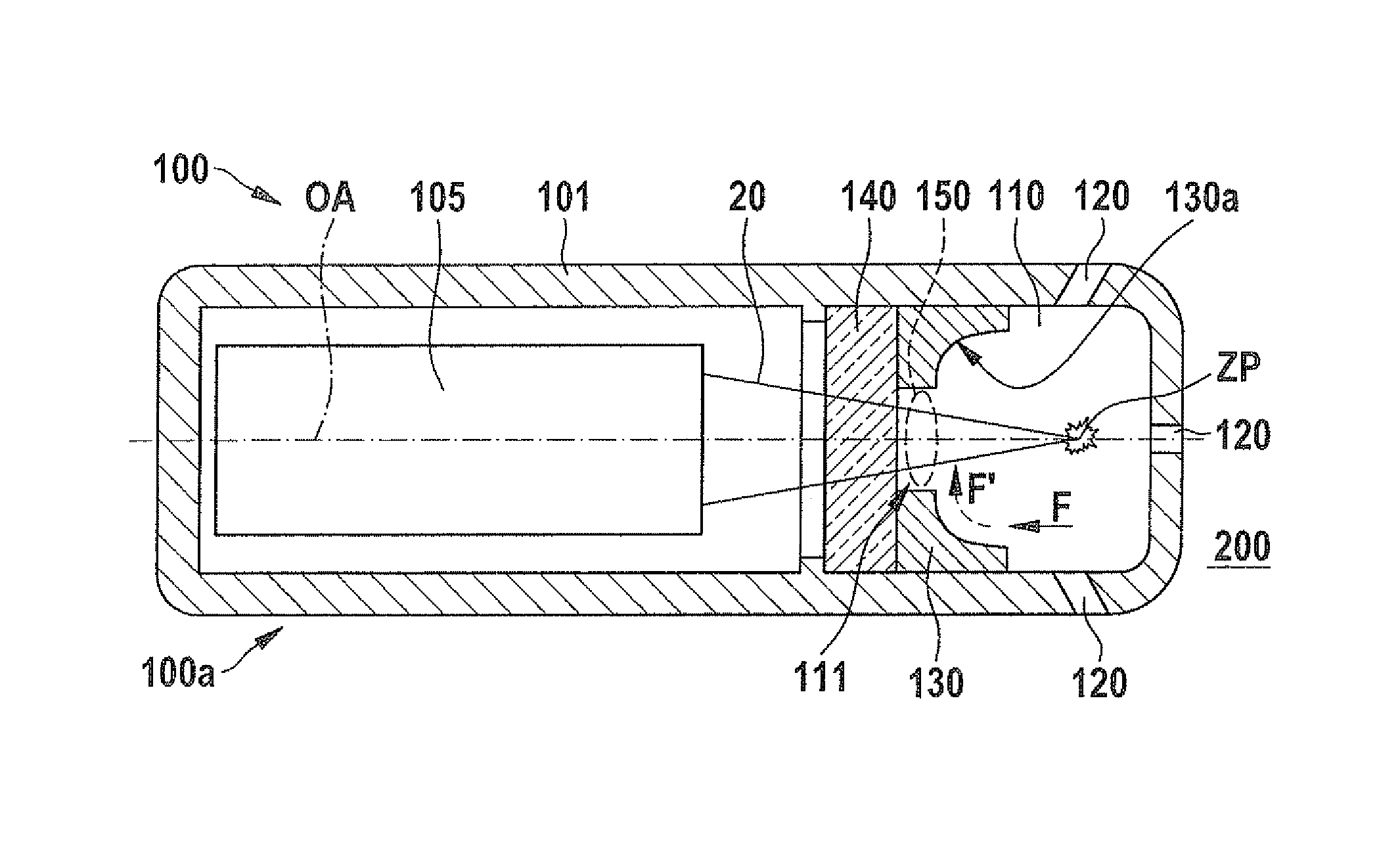
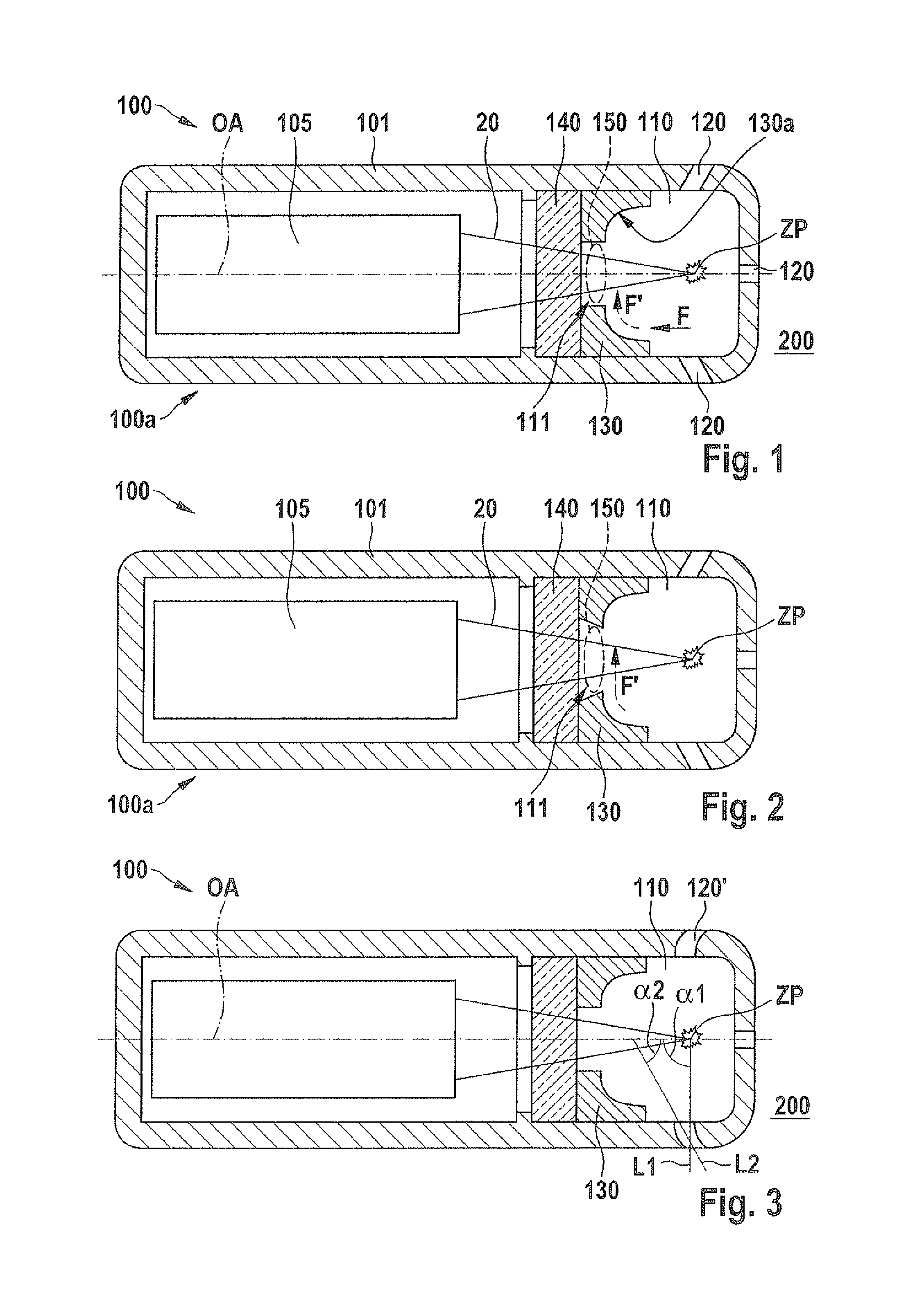
[0009]A particularly efficient deflection of the fluid flows interfering with the residual gas blanket formation is possible according to the present invention in that the flow-guiding element has a flow-guiding surface which has an essentially concave design. Other variants of the present invention may also provide flow-guiding surfaces which are concave only sectionally, for example, as long as the fluid flow is prevented from directly acting on the combustion chamber window surface or an adjoining volume region.
[0011]In another very advantageous specific embodiment of the laser spark plug according to the present invention it is provided that the flow-guiding element is situated directly in the area of the combustion chamber window, thus resulting in additional mechanical protection of the volume region in the area of the combustion chamber window in which the formation of the desired residual gas blanket is intended.
[0014]In another variant of the present invention, a particularly stable configuration is provided if the flow-guiding element is designed as a single piece together with a housing of the laser spark plug.
[0015]Another very advantageous specific embodiment of the laser spark plug according to the present invention is characterized in that at least one overflow passage is provided, which enables a fluid connection between the antechamber and a combustion chamber, and that the overflow passage is curved. Due to the nature according to the present invention of the curvature of the overflow passage, in contrast to the overflow passages which are conventionally designed as bore holes, an additional degree of freedom is achieved for the guidance of a fluid flow in the interior of the antechamber, thus advantageously supporting the flow-guiding elements according to the present invention with regard to a desired fluid deflection.

Problems solved by technology

The disadvantage of the known laser spark plug is the fact that a residual gas blanket made of a combusted air / fuel mixture cannot form or be preserved on a surface area of the combustion chamber window facing the antechamber, the residual gas blanket being capable of contributing to the protection of the combustion chamber window against the continuous input of additional combustion products.

Method used


Image

  • Laser spark plug
  • Laser spark plug

Examples


Embodiment Construction

[0020]FIG. 1 shows a partial cross section of a first specific embodiment of a laser spark plug 100 according to the present invention. Laser spark plug 100 has an integrated laser device 105 which may generate laser radiation 20 and focus it onto ignition point ZP lying in an antechamber 110 of laser spark plug 100.

[0021]Alternatively, laser spark plug 100 may also be configured in such a way that it is supplied with laser radiation by a remotely situated source (not shown) which it focuses onto the ignition point. In this case, local laser device 105 may be dispensed with.

[0022]The interior of antechamber 110 is separated from part 100a of laser spark plug 100, facing away from the combustion chamber, by a combustion chamber window 140.

[0023]Laser spark plug 100 or its antechamber 110 further has overflow passages 120 which enable a fluid connection between antechamber 110 and an outside area 200, which may involve a combustion chamber of the internal combustion engine, for exampl...


PUM


Abstract

A laser spark plug, e.g., for an internal combustion engine of a motor vehicle or a heavy-duty gas engine, has an antechamber for receiving an ignitable medium and a combustion chamber window which separates the antechamber from a part of the laser spark plug facing away from the combustion chamber. At least one flow-guiding element is provided in the antechamber and is situated in such a way that it deflects a fluid flow, which occurs in the antechamber and moves toward the combustion chamber window, into a radially inner direction.

Description

BACKGROUND OF THE INVENTION[0001]1. Field of the Invention[0002]The present invention relates to a laser spark plug, in particular for an internal combustion engine of a motor vehicle or a heavy-duty gas engine, having an antechamber for receiving an ignitable medium and a combustion chamber window which separates the antechamber from the part of the laser spark plug facing away from the combustion chamber.[0003]2. Description of Related Art[0004]A laser spark plug of this type is already known from published German patent application document DE 10 2006 018 973 A1. The disadvantage of the known laser spark plug is the fact that a residual gas blanket made of a combusted air / fuel mixture cannot form or be preserved on a surface area of the combustion chamber window facing the antechamber, the residual gas blanket being capable of contributing to the protection of the combustion chamber window against the continuous input of additional combustion products.BRIEF SUMMARY OF THE INVENTI...

Claims


Application Information

Patent Timeline
Patent Type & Authority Patents(United States)
IPC IPC(8): F02P23/04F02B19/04F02B19/12F02C7/264F02P13/00
CPCF02P23/04F02B19/04F02C7/264F02P13/00F02B19/12Y02T10/125Y02T10/12
Inventor WEINROTTER, MARTINORLANDINI, IGORHERDEN, WERNERWOERNER, PASCALRAIMANN, JUERGEN
Owner ROBERT BOSCH GMBH
Learn More