
Post anchor apparatus and method of use

a technology of post anchors and anchors, which is applied in the direction of buildings, buildings, constructions, etc., can solve the problems of too large holes, too difficult and laborious digging, and inconvenient use,

Inactive Publication Date: 2014-09-23
DUBOSE IND
View PDF16 Cites 4 Cited by
  • Summary
  • Abstract
  • Description
  • Claims
  • Application Information

AI Technical Summary

Benefits of technology

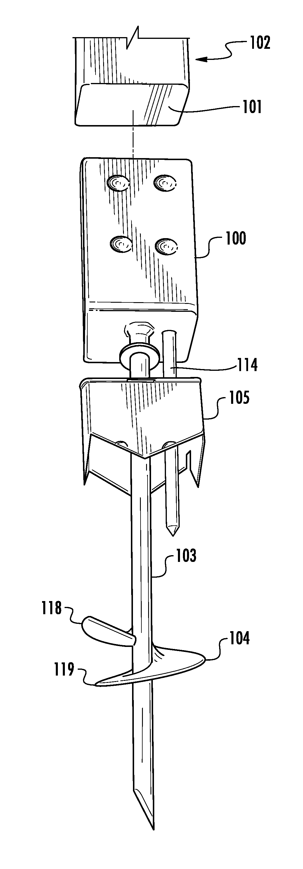
[0014]The post anchoring system further comprises a rod that is driven into the terrain. The rod of the present invention may comprise one or more auger blades which upon rotation promotes downward movement of the rod and auger blade through the terrain. The rod of the present invention may further comprise a stop and a washer engaged thereto. Said stop and washer serve to restrict the relative movement of a stabilizer, which is also engaged to rod. Said stabilizer comprises a top face and at least four side faces and a bore hole within said top face for receiving the rod of the anchoring system of the present invention. In one embodiment, stabilizer is engaged to rod wherein it is allowed to freely rotate about the axis of the rod and move vertically up and down the rod. In another embodiment, side faces comprise ground penetrating members which may be driven in the terrain to provide additional support to the post anchor system of the present invention. In a further embodiment the stabilizer comprises an additional bore hole which au ns with a matching bore hole on the closed end of the housing, each designed to receive the crank pin preventing rotational movement of the anchoring system as well as offering additional stability.

Problems solved by technology

Certain soil conditions may result in hole that is too large or make digging too difficult and strenuous.
The application and mixing of concrete is also labor intensive, strenuous, and time consuming.
If wooden, the buried portion of the post will degrade over time due to moisture exposure and the post strength will weaken potentially resulting in a break or crack of the wood.
However, these devices generally lack acceptance in the industry because they are difficult or inconvenient to install and / or they lack sufficient structural resistance properties once installed to acceptably resist motion of the post above the ground.
Furthermore, they may be expensive when compared to the conventional dig and concrete method.
They also do not solve the problem of increased weakness in the post due to degradation from moisture exposure.

Method used


Image

  • Post anchor apparatus and method of use
  • Post anchor apparatus and method of use
  • Post anchor apparatus and method of use

Examples


Embodiment Construction

[0015]Further scope of applicability of the present invention will become apparent from the description of representative embodiments provided herein. However, it should be understood that the description and specific examples, while indicating embodiments of the invention, are given by way of illustration only, since various changes and modifications within the spirit and scope of the invention will become apparent to those skilled in the art.

[0016]Referring now to FIG. 1, the post anchor system illustrated therein generally comprises housing 100 for receiving a base 101 of a post 102, a rod 103, at least one auger blade 104, and a stabilizer 105.

[0017]The housing 100 depicted in FIGS. 1 and 2 is generally square or rectangular shaped, but it should be recognized by one of ordinary skill in the art that housing 100 may be configured to receive posts of any size and shape. Housing 100 must be sufficiently large of deep to receive enough of the base 101 of post 102 to vertically stab...


PUM


Abstract

Herein described is a post anchor apparatus and methods of use in erecting and anchoring posts in natural terrain. The apparatus of the present invention provides a convenient means of erecting a post in natural terrain while also providing improved strength, stability, and durability to the post. The apparatus comprises at least a housing for receiving the base of a post, a rod, stabilizer element for stabilizing the apparatus within the natural terrain, and an auger blade for driving the rod into the natural terrain.

Description

RELATED APPLICATIONS[0001]This application claims priority to U.S. Provisional Patent Application Ser. No. 61 / 672,980 filed Jul. 18, 2012. The disclosure of U.S. Provisional Patent Application 61 / 672,980 is incorporated by reference herein in its entirety.BACKGROUND OF THE INVENTION[0002]Anchoring a post in the ground typically involves the following steps. First, one must dig a deep narrow hole, insert the pole therein, partially fill the hole with concrete around the perimeter of the post, backfill the soil, and then add water. Following the setting of the concrete, installation of the fencing material may occur, unless the purpose is to install a bird house or a mail box in Which case it is likely already attached to the post.[0003]This method may be inexpensive but several disadvantages exist. Certain soil conditions may result in hole that is too large or make digging too difficult and strenuous. Digging equipment may be required. The application and mixing of concrete is also...

Claims


Application Information

Patent Timeline
Patent Type & Authority Patents(United States)
IPC IPC(8): E02D7/22E04H17/26
CPCE02D7/22E04H17/263E04H17/22E04H12/2223E04H12/2269E04H17/009
Inventor LEE, RICHARD
Owner DUBOSE IND
Learn More