
Optical profilometer using liquid crystal fabry-perot to project fringe pattern

a technology of optical surface profilometer and fringe pattern, which is applied in the field of optical surface profilometer and surface profile measurement method using optical surface profilometer, can solve the problems of difficult to accurately measure the 3d surface map, difficult to acquire 3d depth difference information of objects, and conventional optical surface profilometers with 2-ambiguity problems

Active Publication Date: 2014-09-16
KYUNGPOOK NAT UNIV IND ACADEMIC COOP FOUND
View PDF2 Cites 0 Cited by
  • Summary
  • Abstract
  • Description
  • Claims
  • Application Information

AI Technical Summary

Problems solved by technology

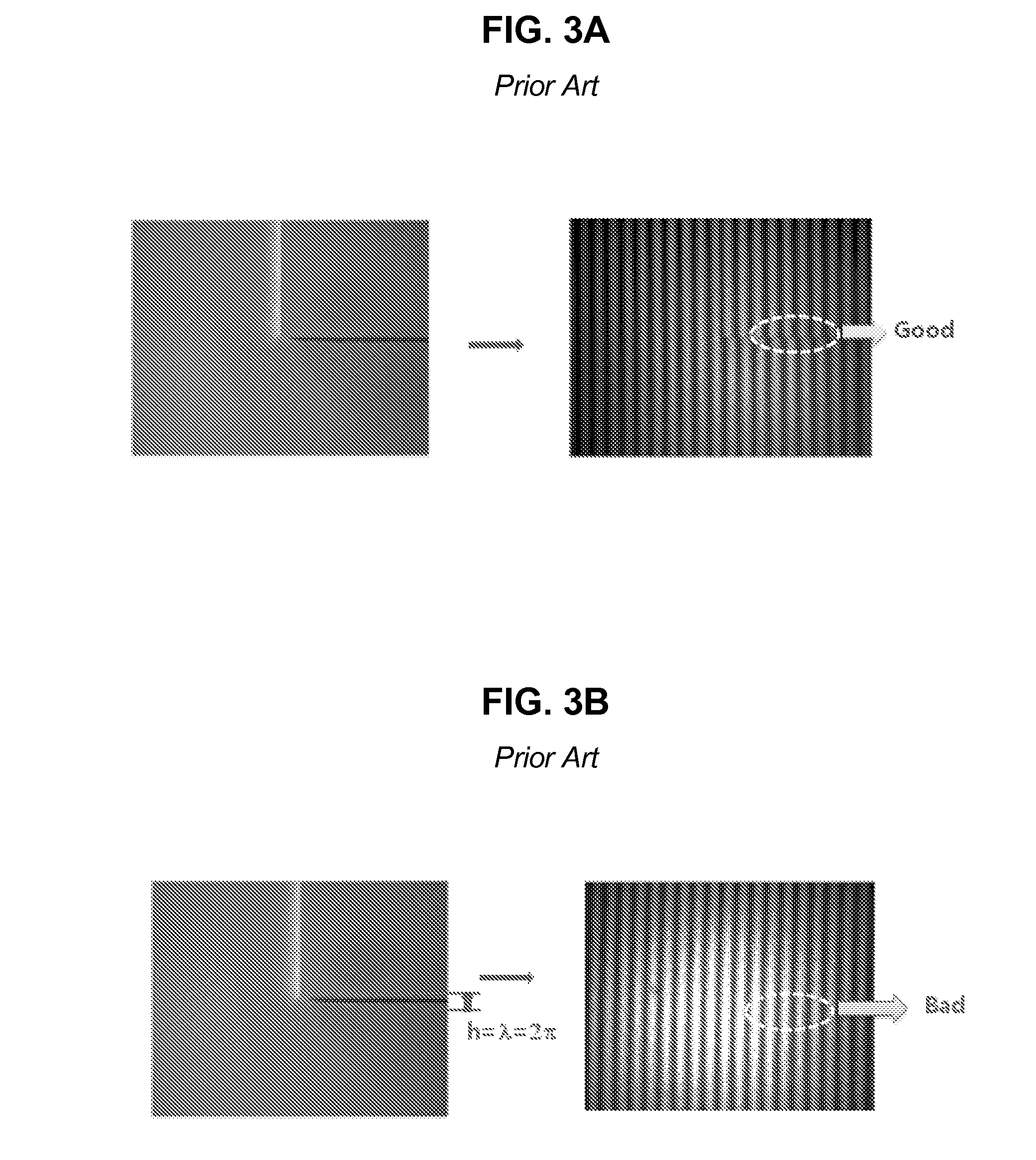
However, referring to FIG. 3B, in the case where an object has a depth difference of which the height is equal to the period of the interference fringes as illustrated in the left picture, when the uniform interference pattern is illuminated on the surface of the object, a uniform interference pattern occurs as illustrated in the right picture, so that it is difficult to acquire 3D depth difference information of the object.
In this manner, conventional optical surface profilometers have the 2π-ambiguity problem caused by the periodicity of the interference pattern.
In other words, there is a problem in that, if the step difference in the surface of the object is larger than one period (2π) of the interference fringes, it is difficult to accurately measure the 3D surface map.
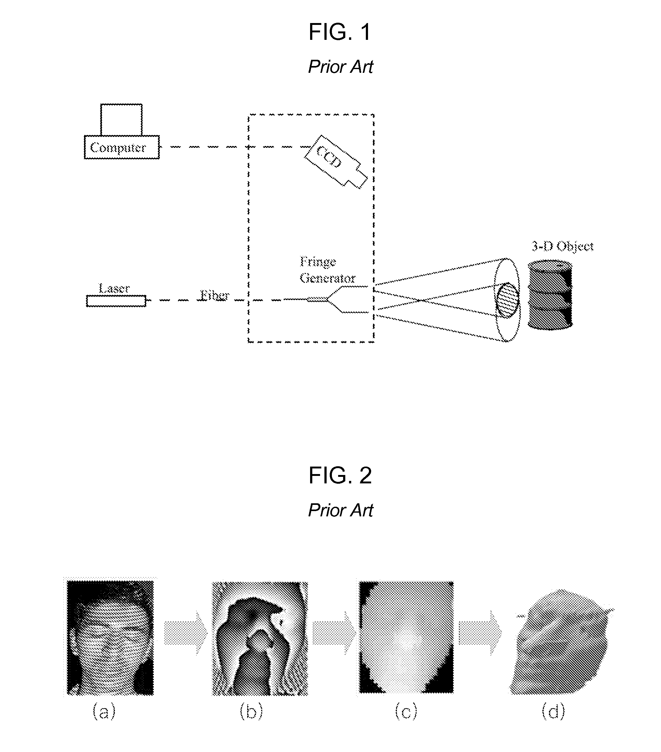
However, in this method, although a change of the surface profile of the object can be accurately measured, hardware units for forming multiple optical patterns need to be additionally provided, so that the size of the apparatus and the costs are increased.

Method used


Image

  • Optical profilometer using liquid crystal fabry-perot to project fringe pattern
  • Optical profilometer using liquid crystal fabry-perot to project fringe pattern
  • Optical profilometer using liquid crystal fabry-perot to project fringe pattern

Examples


Embodiment Construction

[0026]Optical Surface Profilometer

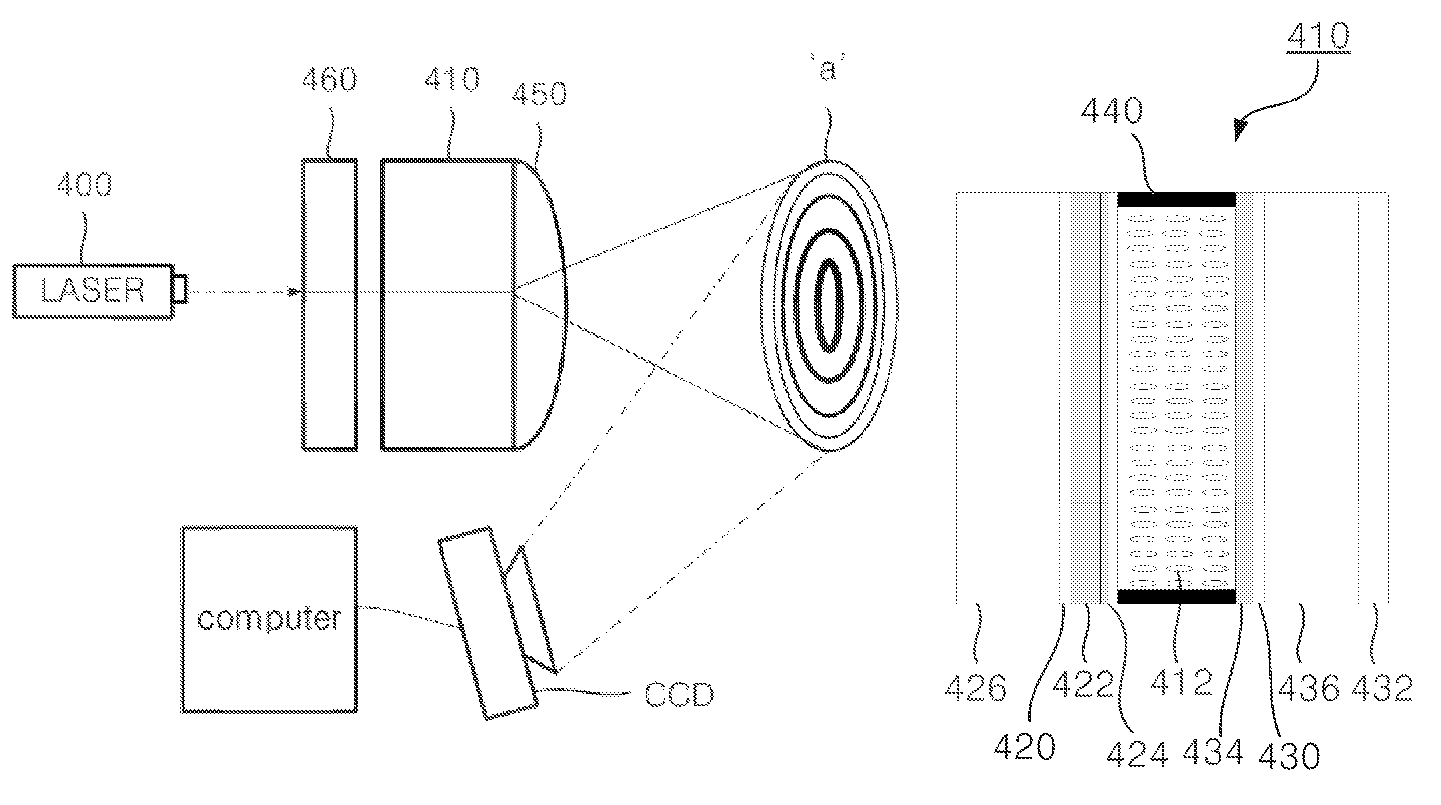
[0027]Hereinafter, a configuration and operations of an optical surface profilometer according to a preferred embodiment of the present invention will be described with reference to the attached drawings. In the optical surface profilometer according to the embodiment, an interference pattern including concentric circular fringes is scanned by using a Fabry-Perot resonator in which liquid crystals are injected, a movement of the interference pattern is induced by changing a resonance condition of the Fabry-Perot resonator, so that a dynamic interference pattern can be generated.

[0028]FIG. 4 is a diagram illustrating an overall configuration of the optical surface profilometer according to the preferred embodiment of the present invention. FIG. 5 is a cross sectional view illustrating a Fabry-Perot resonator 410 of FIG. 4. Referring to FIGS. 4 and 5, the optical surface profilometer 40 according to the embodiment includes a light source 400, a Fabry-...


PUM


Abstract

Provided is an optical surface profilometer. The optical surface profilometer includes a Fabry-Perot resonator into which liquid crystals are inserted, a light source which supplies coherent light to the Fabry-Perot resonator, and a convex lens which is disposed in an interference pattern emitting plane of the Fabry-Perot resonator, wherein the coherent light supplied from the light source is incident to the Fabry-Perot resonator, wherein, when the light is incident, the Fabry-Perot resonator emits an interference pattern generated in a resonance mode, and wherein the interference pattern is configured so that a number of circular fringes having the same center are disposed non-linearly. As a voltage is applied to the liquid crystal layer of the Fabry-Perot resonator, an effective refractive index is changed, so that a resonance mode condition of the Fabry-Perot resonator is changed. As a result, a diameter of the interference pattern is also changed. A 3D surface profile of the object is measured by measuring and analyzing the change of the interference patterns.

Description

[0001]This application claims priority to Korean Patent Application No. 10-2010-0003499, filed on Jan. 14, 2010, and all the benefits accruing therefrom under 35 U.S.C §119, the contents of which in its entirety are hereby incorporated by reference.BACKGROUND OF THE INVENTION[0002]1. Field of the Invention[0003]The present invention relates to an optical surface profilometer and a surface profile measuring method using the optical surface profilometer, and more particularly to, a surface profilometer which generates a dynamic interference pattern by using a Fabry-Perot resonator into which liquid crystals are inserted and measures a 3D surface profile of an object by using the dynamic interference pattern and a surface profile measuring method using the surface profilometer.[0004]2. Description of the Prior Art[0005]A 3D surface profilometer is an apparatus for accurately measuring a depth profile of a surface of an object. The 3D surface profilometer has been used as an industrial ...

Claims


Application Information

Patent Timeline
Patent Type & Authority Patents(United States)
IPC IPC(8): G01B11/02G01B11/25H04N7/18
CPCG01B11/25H04N7/18
Inventor KIM, HAK-RINPARK, CHANG-SUB
Owner KYUNGPOOK NAT UNIV IND ACADEMIC COOP FOUND
Learn More