Continuous sterilization system
a sterilization system and continuous technology, applied in the direction of material analysis, instruments, and treatment using wave/particle radiation, can solve the problem of not sterilizing the proportion, and achieve the effect of ensuring a uniform irradiation period and uniform irradiation period
- Summary
- Abstract
- Description
- Claims
- Application Information
AI Technical Summary
Benefits of technology
Problems solved by technology
Method used
Image
Examples
first embodiment
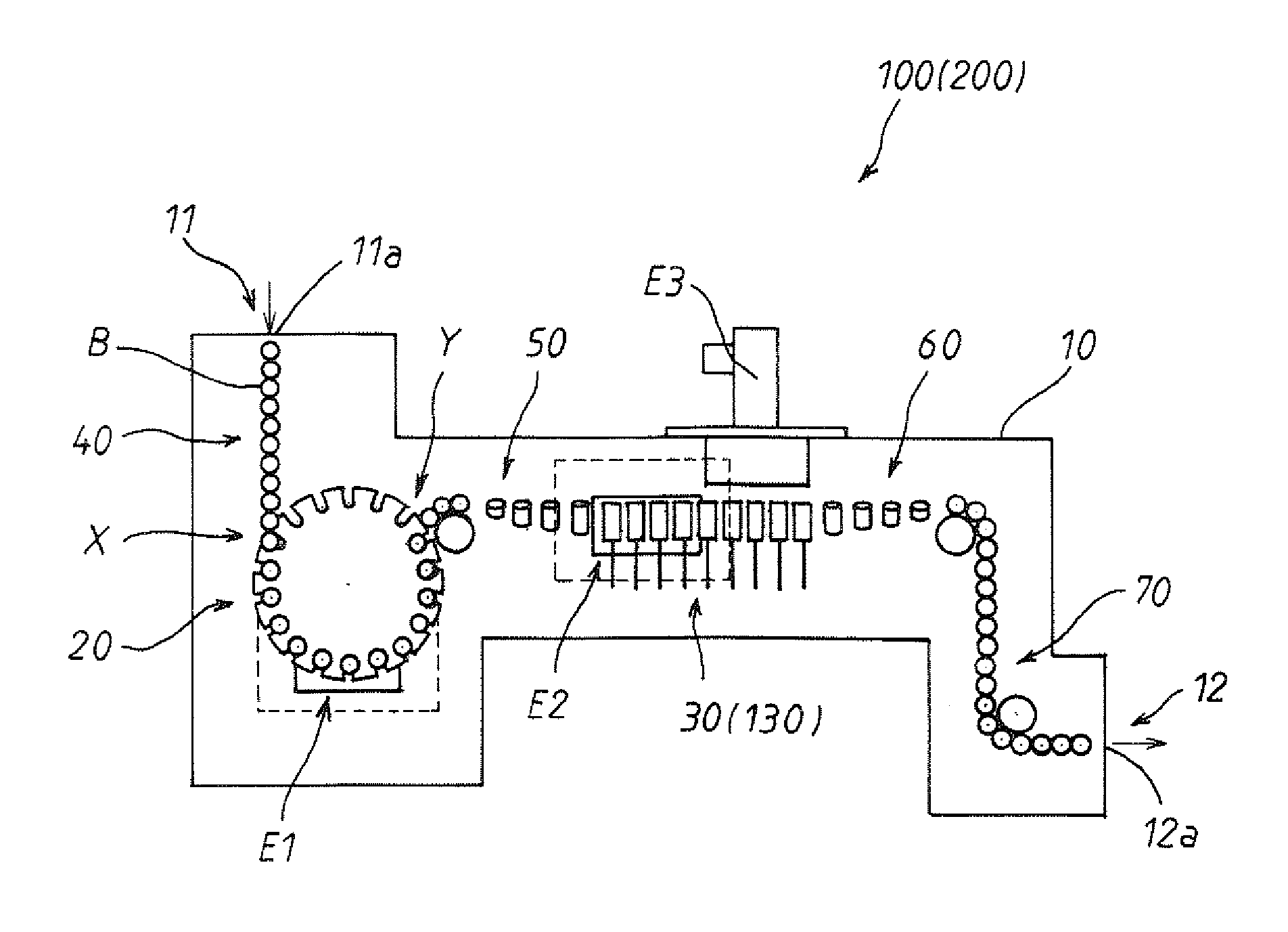
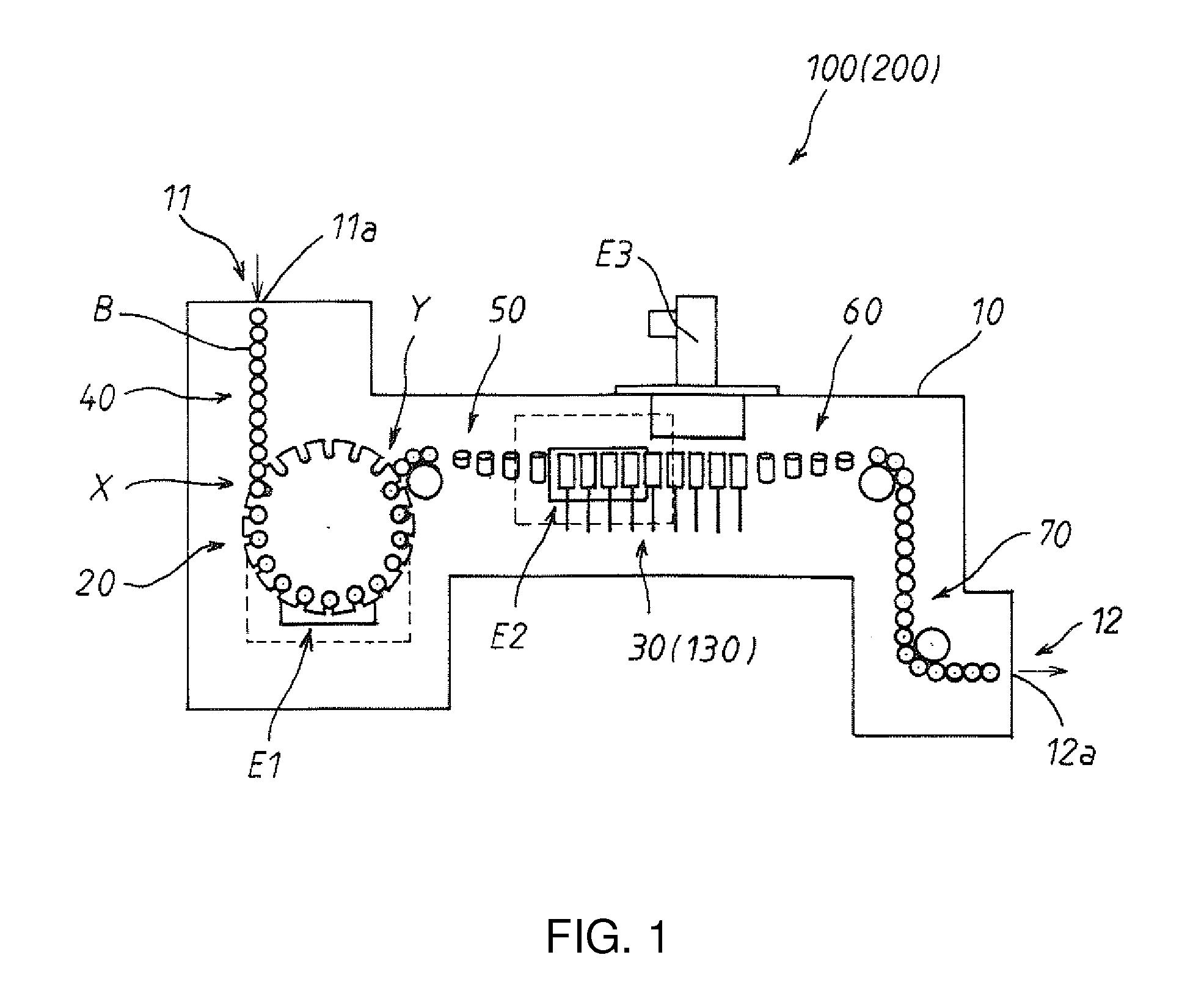
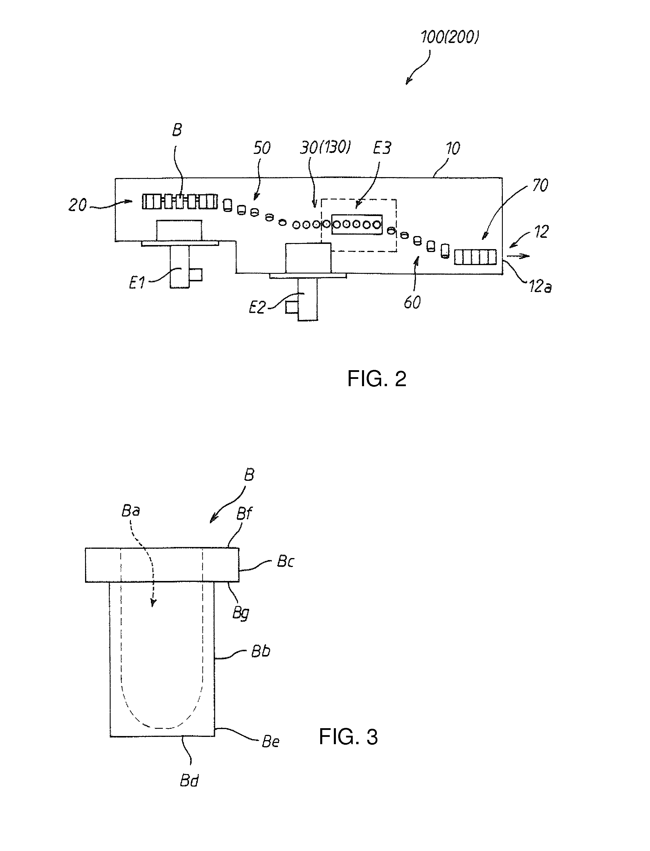
[0166]A first embodiment of a continuous sterilization system according to the present invention will be described below in accordance with the attached drawings. FIG. 1 is a plan view of the continuous sterilization system 100 according to the first embodiment, and this continuous sterilization system 100 is formed of a chamber 10 constituted by a wall portion formed of a metal plate made of stainless in which an X-ray shielding material (not shown) is bonded inside and is installed consecutively to an aseptic workroom (not shown) in which a pharmaceutical product is filled on a right-side side surface in the illustration.
[0167]On a left-side rear surface of the chamber 10 (upper left side in FIG. 1), a carrying-in port 11 through which a cylindrical container B to be sterilized is carried into the chamber 10 is provided, and a shutter 11a capable for being opened / closed is provided at this carrying-in port 11. Moreover, on the right-side side surface of the chamber 10, a carrying-...
second embodiment
[0228]Subsequently, a second embodiment of a continuous sterilization system according to the present invention will be described in accordance with the attached drawings. The continuous sterilization system 200 according to the second embodiment has a structure similar to that of the first embodiment except that the adsorption conveyer mechanism 30 in the first embodiment is changed to a chucking conveyer mechanism 130 (See FIGS. 1, 2, and 4). Moreover, a sterilization target to be sterilized by the continuous sterilization system according to the second embodiment is also the cylindrical container B having the structure similar to that of the first embodiment (See FIG. 3).
[0229]That is, inside the chamber 10, the star-wheel conveyer mechanism 20 and the chucking conveyer mechanism 130 for supporting and conveying the cylindrical container B in order to emit the electron beam as well as the three electron beam accelerators E1, E2, and E3 for irradiating the electron beam to each po...
third embodiment
[0262]Subsequently, a third embodiment of a continuous sterilization system according to the present invention will be described in accordance with the attached drawings. In the continuous sterilization system 300 according to the third embodiment, the position of the star-wheel conveyer mechanism 20 and the position of the adsorption conveyer mechanism 30 in the first embodiment are exchanged with each other. Moreover, the spiral chute mechanism 50 in the first embodiment is changed to a screw-conveyer mechanism 80, while the other portions have a structure similar to that of the first embodiment (See FIGS. 16, 17, and 18). Moreover, a sterilization target to be sterilized by the continuous sterilization system according to this third embodiment is also the cylindrical container B having the structure similar to that of the first embodiment (See FIG. 3).
[0263]That is, inside the chamber 10, the star-wheel conveyer mechanism 20 and the adsorption conveyer mechanism 30 for supporting...
PUM
| Property | Measurement | Unit |
|---|---|---|
| acceleration voltage | aaaaa | aaaaa |
| acceleration voltage | aaaaa | aaaaa |
| size | aaaaa | aaaaa |
Abstract
Description
Claims
Application Information
 - R&D
- Intellectual Property
- Life Sciences
- Materials
- Tech Scout
- Unparalleled Data Quality
- Higher Quality Content
- 60% Fewer Hallucinations
Browse by: Latest US Patents, China's latest patents, Technical Efficacy Thesaurus, Application Domain, Technology Topic, Popular Technical Reports.
© 2025 PatSnap. All rights reserved.Legal|Privacy policy|Modern Slavery Act Transparency Statement|Sitemap|About US| Contact US: help@patsnap.com


