Probe alignment tool for the scanning probe microscope

a scanning probe and alignment tool technology, applied in scanning probe techniques, instruments, nanotechnology, etc., can solve the problems of prior art innovations and systems that do not include direct viewing of the probe tip itself, and achieve the effect of convenient replacement and alignment positioning

Inactive Publication Date: 2014-09-09
AFSHARI ALI R
View PDF3 Cites 2 Cited by
  • Summary
  • Abstract
  • Description
  • Claims
  • Application Information

AI Technical Summary

Benefits of technology

[0010]In accordance with the instant invention there is provided a method and apparatus for directly observing a probe tip and positioning said probe tip precisely and accurately with respect to a target sample workpiece of interest. It is contemplated that the instant invention will be utilized with a scanning probe optical microscope system comprising an optical microscope sub system coupled with an atomic force scanning microscope sub system and in which the optical microscope is first employed to acquire a region within which resides an area to be more minutely examined by the atomic force scanning microscope. The advantages of the invention further provide for convenient replacement and alignment positioning of probe tips in the atomic force scanning probe microscope sub system.

Problems solved by technology

These prior art innovations and systems, however, do not include those elements of the instant invention that provide a long felt but unmet need in the art.
None of the prior art has used the direct viewing of the probe tip itself as a means for positioning and aligning that probe tip with respect to a sample work piece of interest.

Method used


Image

  • Probe alignment tool for the scanning probe microscope
  • Probe alignment tool for the scanning probe microscope
  • Probe alignment tool for the scanning probe microscope

Examples


Embodiment Construction

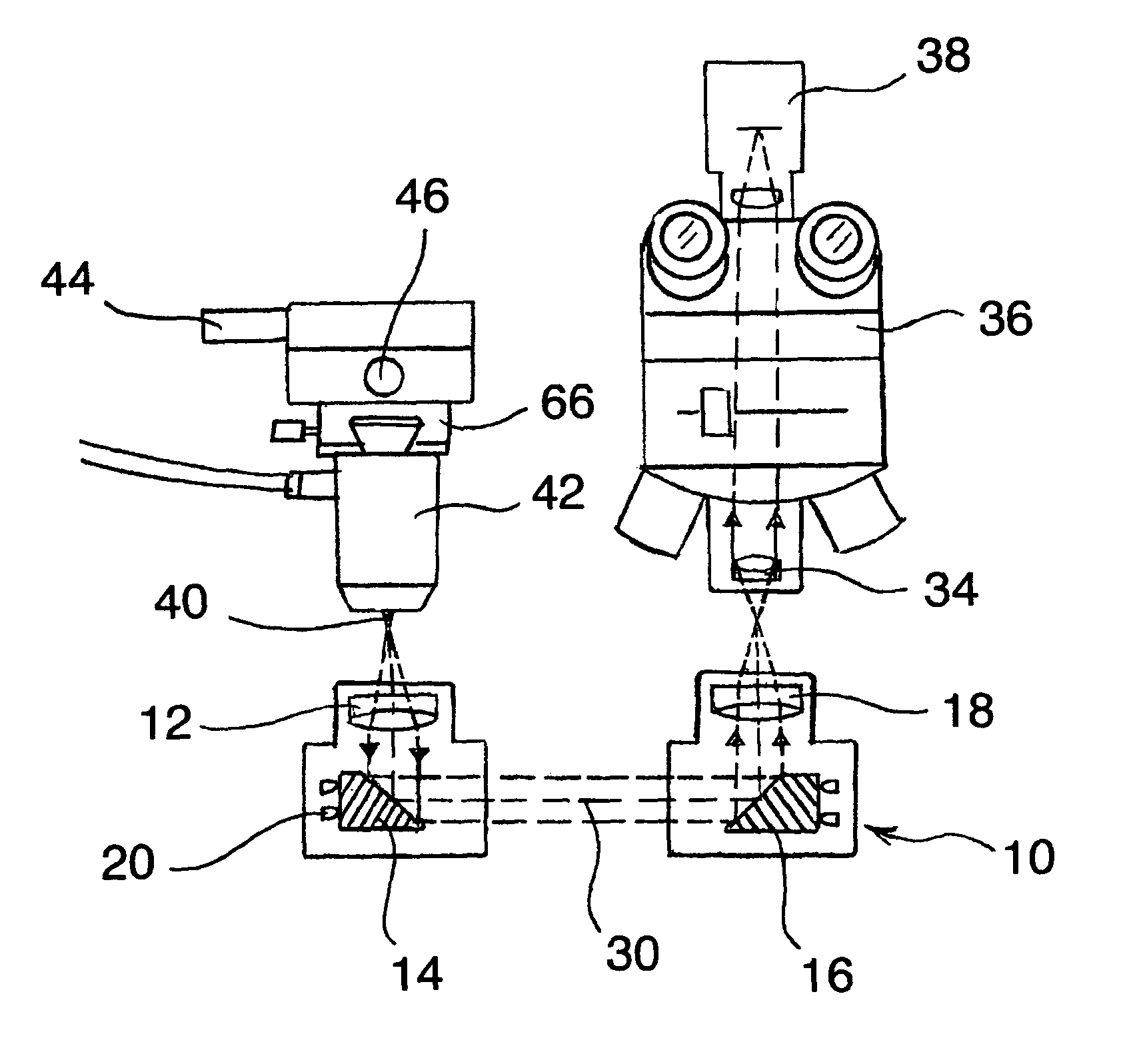
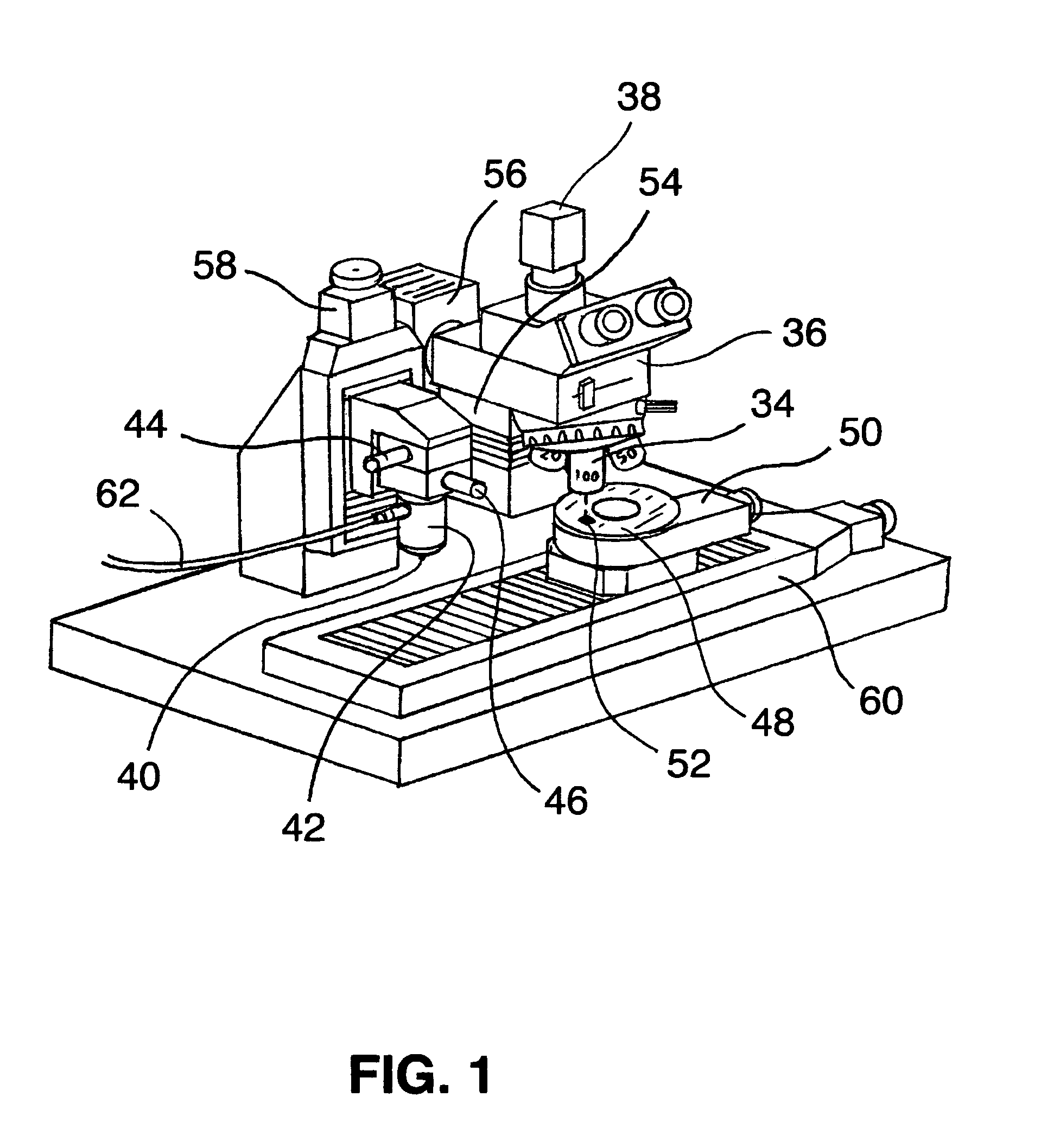
[0020]Referring to the drawing and to FIGS. 3, 4 and 5 with greater particularity, an initial set-up of alignment tool 10 may be explained. Alignment tool 10 comprises a relay optic that projects the frontal, as opposed to side or profile, image of atomic force microscope probe tip 40 to an observer, for example, to the focal point of microscope objective 34 of optical microscope 36 for direct human observation or perhaps concurrently to the sensory facilities of a CCD camera, 38, for display on a monitor, not shown. The optical design of alignment tool 10 includes two microscope objectives, 12 and 18 and two adjustable fold mirrors, 14 and 16. First objective 12 projects an image of probe tip 40 to selected objective 34 on the turret of optical microscope 36 by way of first fold mirror 14 to second fold mirror 16 and alignment tool relay second objective 18. Fold mirror tilt adjustment screws 20 provide for adjustment of the fold mirrors 14 and 16 respectively. Mounting bores 26 ar...


PUM


Abstract

A probe alignment tool (10) for scanning probe microscopes utilizes an attached relay optics to view the scanning probe microscope probe tip (40) and align its image in the center of the field of view of an optical microscope (36). Adjustments to optical microscope motorized stages (50) and (60) along with adjustments of scanning probe microscope stages (44), (46) and (58) allow determination of a path and distance from the center of the field of view to the probe tip (40). From such determination a target area to be examined by the scanning probe microscope may be positioned precisely and accurately under the probe tip (40). Replacement of a scanning probe microscope probe tip (40) in an atomic force microscope unit (42) may be accomplished without the loss of alignment measurements.

Description

TECHNICAL FIELD[0001]This invention relates to scanning probe microscope systems. The invention is, however, more particularly directed to apparatus and methods for alignment and positioning of scanning probe microscope probe tips.BACKGROUND ART[0002]The scanning probe microscope is a general term referring to various mechanisms and methods in which a sample is scanned with a microscopic probe to produce much higher resolutions than can be achieved with standard optical microscopes. One common example is the atomic force microscope, also known as the scanning force microscope that scans a sharp stylus attached to a flexible spring lever, commonly called a cantilever, over a sampled surface. This very high resolution atomic force microscope has a demonstrated resolution of fractions of a nanometer more than one thousand times better than the optical diffraction limit. The basic objective of the operation of the atomic force microscope is to measure the forces at the atomic level betw...

Claims


Application Information

Patent Timeline
Patent Type & Authority Patents(United States)
IPC IPC(8): G01Q20/00B82Y35/00G01Q30/02G01Q40/00
CPCG01Q40/00G01Q30/025B82Y35/00
Inventor AFSHARI, ALI, R.
Owner AFSHARI ALI R
Why Eureka
Try Eureka