
Method and device for asynchronous communication of data on a single conductor

a technology of asynchronous communication and data, applied in the field of data communication, can solve the problems of large number of conductors, large power consumption of very numerous interconnections between circuit elements, and the difficulty of obtaining synchronous operation (that is to say using one and the same clock domain) in a complete circuit and/or in a stack of circuits, so as to reduce the number of conductors

Inactive Publication Date: 2014-09-09
COMMISSARIAT A LENERGIE ATOMIQUE ET AUX ENERGIES ALTERNATIVES
View PDF6 Cites 2 Cited by
  • Summary
  • Abstract
  • Description
  • Claims
  • Application Information

AI Technical Summary

Benefits of technology

The invention proposes a method for reducing the number of conductors in an asynchronous communication system. This is achieved by "forcing" the exchange conductor, which means the sender or receiver applies a potential to the conductor, and then allowing the Other side to force the conductor. This relaxation of the forcing action can be achieved by either placing the conductor at high impedance or using a small transistor to hold it at its potential. The invention also introduces threshold-based detectors that can detect the switching of data input from one level to another and interrupt the forcing of the output to the intermediate level after detecting the switching.

Problems solved by technology

One of the problems which arises is the complexity and the power consumption of the very numerous interconnections between circuit elements.
A second problem, related to the complexity and to the variations in advanced technologies, is the great difficulty of obtaining synchronous operation (that is to say using one and the same clock domain) in a complete circuit and / or in a stack of circuits.
A drawback of asynchronous communications is therefore the use of a larger number of conductors than for synchronous communications.

Method used


Image

  • Method and device for asynchronous communication of data on a single conductor
  • Method and device for asynchronous communication of data on a single conductor
  • Method and device for asynchronous communication of data on a single conductor

Examples


Embodiment Construction

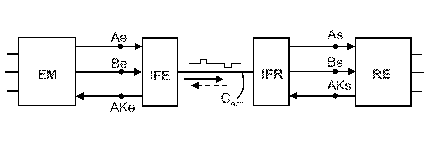
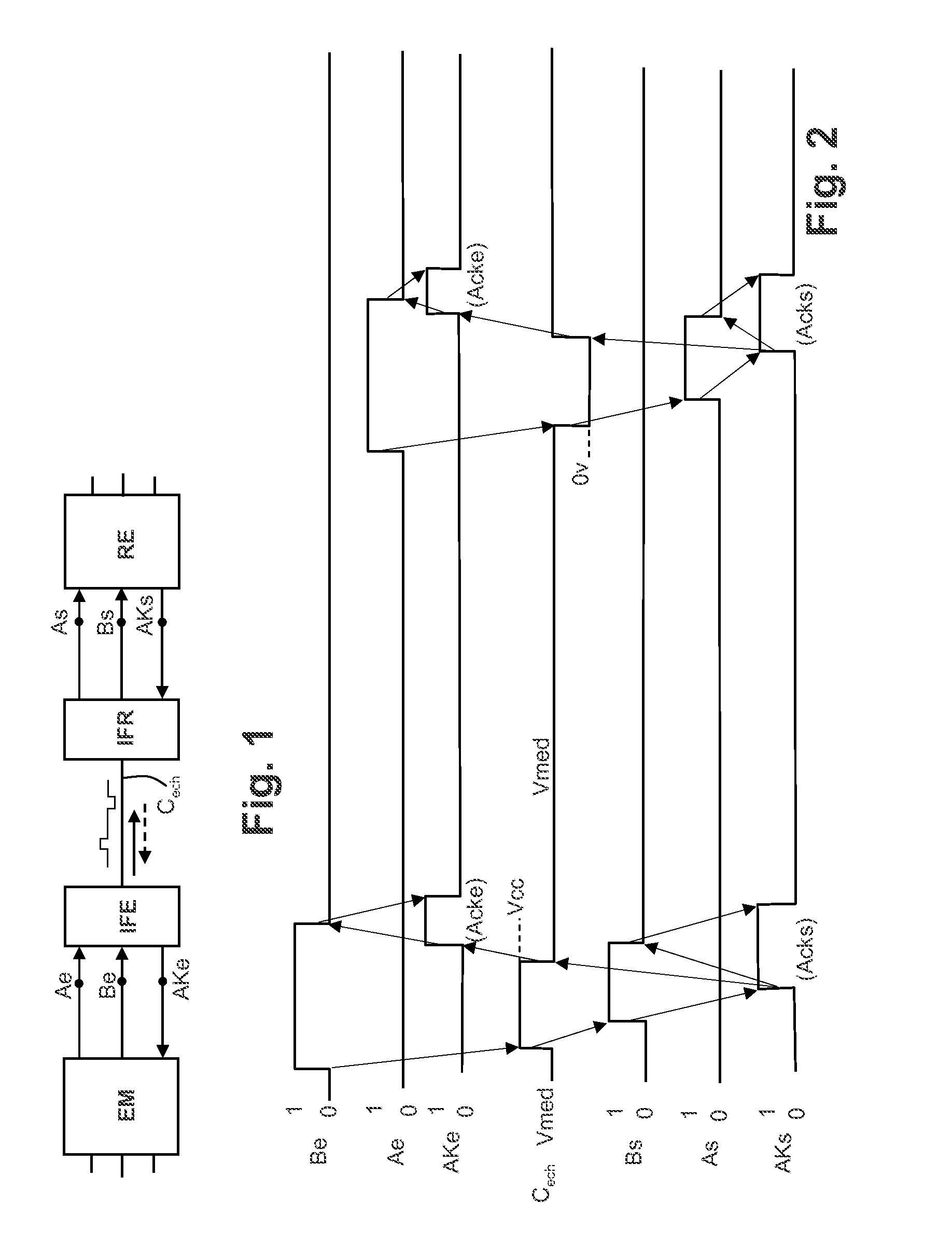
[0033]FIG. 1 represents the general principle of the asynchronous communication according to the invention between a sender EM and a receiver RE. The sender EM is associated with a send interface circuit IFE, and the receiver is associated with a receive interface circuit IFR. The two interface circuits IFE and IFR communicate through a single exchange conductor Cech which transmits one by one the binary data 0 or 1 from the sender to the receiver, and which transmits from the receiver to the sender, after each data item, an acknowledgment signal indicating that the receiver has indeed received the data item sent by the sender.

[0034]To simplify the explanations, it is assumed that the sender is connected to the send interface by three terminals which are terminals Ae, Be, and AKe, and it is assumed that the sender is supplied between a ground potential 0 volts and a general power supply potential Vdd. The terminal Ae serves to transmit the 0 logic levels from the sender to the send ...


PUM


Abstract

The invention relates to the asynchronous communication of data in complex integrated systems, be it inside integrated circuit chips or between integrated circuit chips, for example in a compact stack of chips. According to the invention, the transmission is done on a single conductor of exchanges. The data are transmitted on this conductor in the form of at least three levels of potential, the first level representing a first value of data item transmitted, the second representing a second value of data item transmitted, and the third representing an inactive level. An acknowledgment signal is transmitted on the same exchange conductor as the data. This signal is preferably sent by the receiver in the form of the forcing of the exchange conductor by the receiver to the inactive potential level, the sender detecting this forcing.

Description

CROSS-REFERENCE TO RELATED APPLICATION[0001]This application claims priority to foreign French patent application No. FR 1059565, filed on Nov. 19, 2010, the disclosure of which is incorporated by reference in its entirety.FIELD OF THE INVENTION[0002]The invention relates to the communication of data in complex integrated systems, be it inside integrated circuit chips or between integrated circuit chips, for example in a compact stack of chips.BACKGROUND[0003]One of the problems which arises is the complexity and the power consumption of the very numerous interconnections between circuit elements.[0004]A second problem, related to the complexity and to the variations in advanced technologies, is the great difficulty of obtaining synchronous operation (that is to say using one and the same clock domain) in a complete circuit and / or in a stack of circuits. This difficulty has prompted teams to propose architectures either of “Globally Asynchronous, Locally Synchronous” (GALS) type, in...

Claims


Application Information

Patent Timeline
Patent Type & Authority Patents(United States)
IPC IPC(8): H04L25/34G06F13/42
CPCG06F13/4286
Inventor BELLEVILLE, MARC
Owner COMMISSARIAT A LENERGIE ATOMIQUE ET AUX ENERGIES ALTERNATIVES
Learn More