
Full toroidal traction drive

a full toroidal, traction drive technology, applied in the direction of friction gearings, belts/chains/gearrings, mechanical equipment, etc., can solve the problems of inability to maintain a sufficient ratio change, energy loss associated with supporting rotational loads using bearings considered too high by most designers, and the mechanical problem of full toroidal variator

Inactive Publication Date: 2014-09-09
ULTIMATE TRANSMISSIONS
View PDF20 Cites 41 Cited by
  • Summary
  • Abstract
  • Description
  • Claims
  • Application Information

AI Technical Summary

Benefits of technology

The present invention provides a toroidal variable speed traction drive which includes a driving disc and a driven disc, which are urged together by a clamping force. The discs have rollers interposed between them, which roll on the discs and the toroidal surface of the discs. Each roller is mounted on a rotating axle and is adapted to move to a stable position within a plane where the rollers contact the discs. The first rolling surface is conical to match the surface velocity of the contacting points of the rollers and discs. The rollers are mounted in trunnion supports that allow the discs to move in a direction parallel to the common axis. The drive is lubricated with a traction fluid that increases its viscosity when under pressure and the surface of the rollers and discs are arranged to prevent metal to metal contact between them. The traction fluid has a traction coefficient of greater than 0.05 when subject to a stress of greater than 1 GPa.

Problems solved by technology

Without the use of the double cavity the energy loss associated with supporting the rotational loads using bearings it considered too high by most designers.
The maximum practical number of rollers in the Half and Full Toroidal drives is three after which it becomes impossible to maintain sufficient ratio change.
However the Full Toroidal Variator suffers from a mechanical problem called “spin”.
When relatively high spin occurs the traction coefficient may maintain but a high degree of slip (loss of efficiency) occurs creating an “apparent” lowering of the traction coefficient.
When the spin exceeds certain limits the high temperatures created under the patch will damage the traction fluid.
These high temperatures can also affect the hardness of the steel limiting the types of steel and types of heat treatment process used to harden the components.
Because of the spin problems described earlier associated with Full Toroidal Friction drives, although they could support high power and were relatively efficient, they were subject to fatigue and the moving parts needed replacement often.
The Picanol system does not appear to have been seriously implemented in any commercially available transmission.
It is perceived that the Picanol system would suffer from mechanical difficulties associated with mounting of the rollers.
Although there are no calculations associated with the disclosure it can be understood by someone skilled in the art of traction drives that the clamping arrangement is very light and would not be capable of clamping sufficiently to enable an effective power transfer when using traction oil with a traction coefficient (friction coefficient) of around 0.05.
If such a drive was converted to a traction drive, problems would be encountered with most of its mechanical arrangement if any attempt to increase the power density beyond the current level.
When the clamping pressures are increased the roller support mechanism involving two connected axles described in Picanol become unworkable.
When the clamping forces are high and the width of the conical contacts large in proportion, this will at best lose efficiency and at worst very rapidly collapse the bearings.
Unless the “V” shaped connected axles can displace themselves laterally within the plane that contains them this will load up the bearings and inhibit the force carried by the conical surfaces necessary to transfer load, or damage the bearings, or bend the axles.

Method used


Image

  • Full toroidal traction drive
  • Full toroidal traction drive
  • Full toroidal traction drive

Examples


Embodiment Construction

[0052]A first aim of the invention is to reduce the differential velocities that exist between the rollers and the discs to almost zero in at least one ratio position.

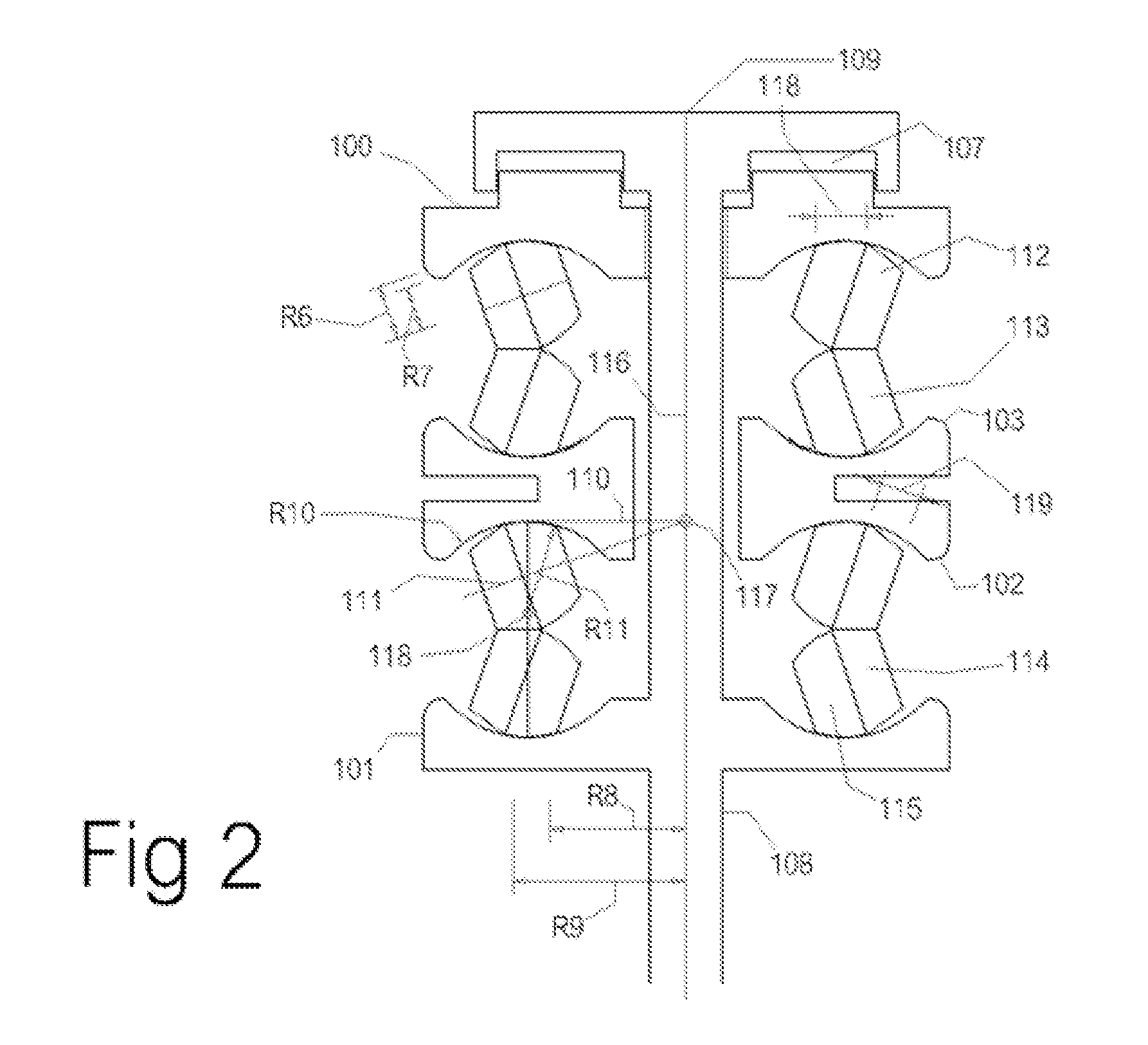
[0053]In order to achieve the first aim, a Full Toroidal Variator that includes the input and output discs shafts bearings and clamping device is selected. FIG. 2 shows diagrammatically such an arrangement. Two rollers 112 and 113 replace the conventional single rollers. These rollers are made with a generally conical rolling surface 114 on which they roll on each other and a generally toroidal surface 115 on which they roll on the discs.

[0054]The conical surface could also be formed with a very large crown radius or with curved edges so as to reduce stress concentrations at the edges of the conical surfaces. This modification is often associated with the design of fixed ratio traction drives involving cylinders or cones. Although not exactly conical the surfaces will control the actual angle adopted by the rollers rel...


PUM


Abstract

A toroidal variable speed traction drive includes a driving disc and a driven disc. The discs have a common axis. A plurality of pairs of contacting rollers are interposed between the discs. The discs are urged together against the roller pairs (A) by a clamping force. Each of the rollers has a first rolling surface, by which it rolls on the other roller of the pair, and a second rolling surface by which it rolls on the toroidal surface of a corresponding disc. Each roller is mounted on a supporting axle about which it can rotate. The rotational axes of the rollers in a pair are supported in a plane that contains the two points where the rollers of the pair contact the discs. At least one of the rollers in each pair is adapted to be moved to adopt a stable position within the plane by the reactionary force exerted on it by the other roller of the pair.

Description

TECHNICAL FIELD[0001]The present invention relates to Continuously Variable Transmissions, particularly of the Full Toroidal Race Rolling Traction Drive type.BACKGROUND OF THE INVENTION[0002]There are several Constantly Variable Transmissions (CVTs) that are being successfully designed and manufactured as transmissions for vehicles and other machines that require changing gear ratios.[0003]The market for these drives within the automotive industry, at least, is generally split between belt drives and traction drives. The present invention is related to traction drives.[0004]The traction drive market is dominated by two similar types of mechanism. One is generally called a Half Toroidal drive and the other a Full Toroidal drive.[0005]Both of these involve the use of twin discs that are machined with the negative shape of a toroid in opposing faces. Between the discs are rollers that roll against the surface of both toroidal cavities and can transfer force and power from one disc to t...

Claims


Application Information

Patent Timeline
Patent Type & Authority Patents(United States)
IPC IPC(8): F16H15/38
CPCF16H15/38
Inventor DURACK, MICHAEL, JAMES
Owner ULTIMATE TRANSMISSIONS
Learn More